Sleeve molding

a technology of injection molding and sleeves, applied in the field of sleeves, can solve the problems of difficult to achieve close dimensional tolerances, difficult to achieve commercial use of pen, and substantially more expensive pen than p

Inactive Publication Date: 2009-11-10
GRAHAM PACKAGING PET TECH
View PDF55 Cites 8 Cited by
  • Summary
  • Abstract
  • Description
  • Claims
  • Application Information

AI Technical Summary

Benefits of technology

[0010]The present invention is directed to a method and apparatus for making a multilayer injection-molded plastic article, such as a prefor

Problems solved by technology

However, PEN is substantially more expensive than PET and has different processing requirements: Thus, at present the commercial use of PEN is limited.
However, this creates several problems.
It is thus difficult to achieve close dimensional tolerances and, in general, the variability of the critical neck

Method used


Image

  • Sleeve molding
  • Sleeve molding
  • Sleeve molding

Examples


Embodiment Construction

First Preform Embodiment (Refillable Water)

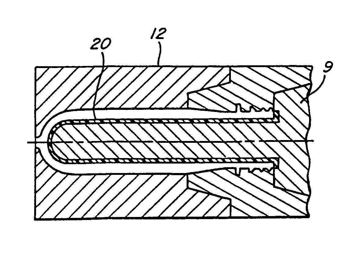
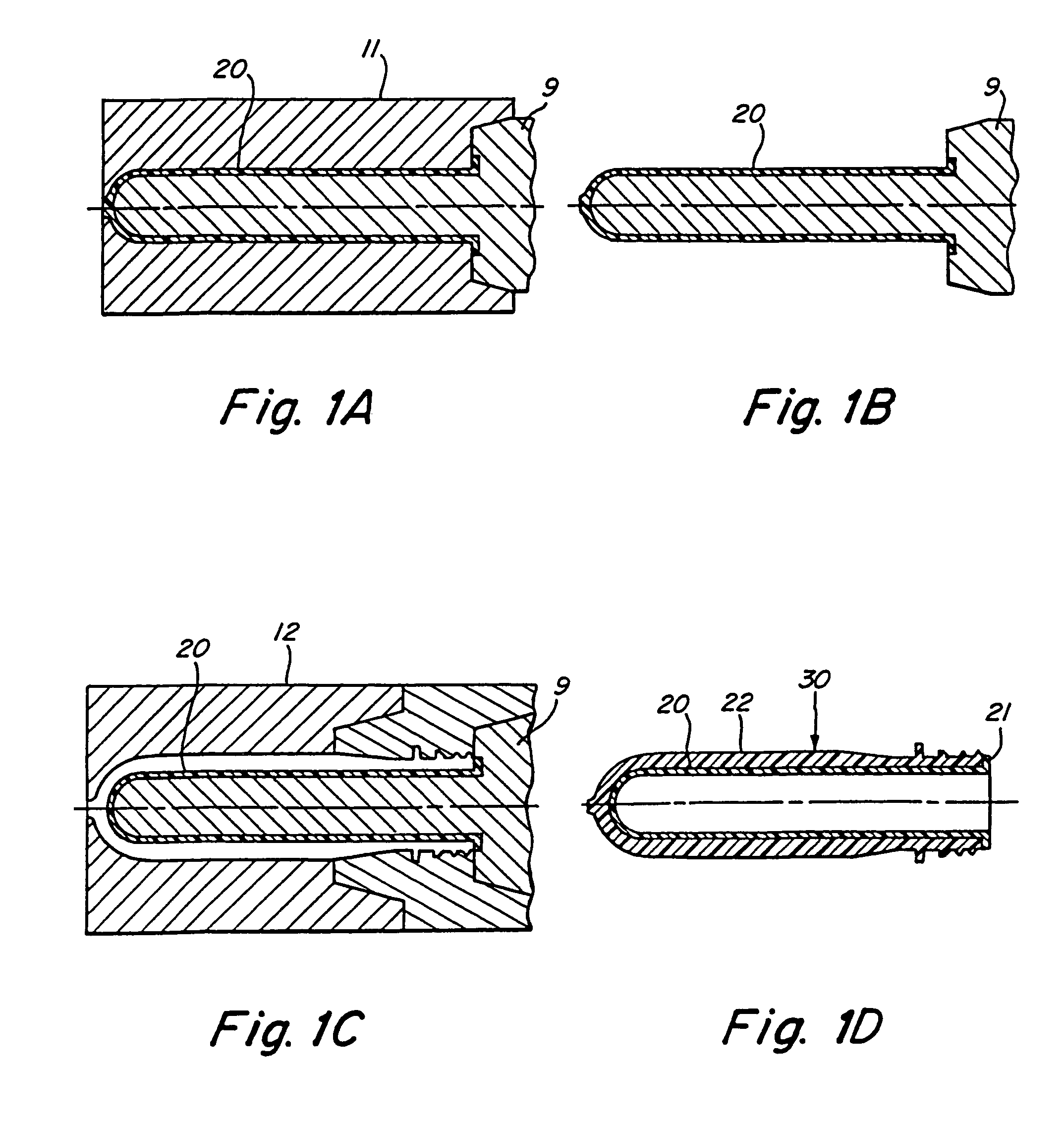
[0036]FIGS. 1A-1D illustrate schematically one method embodiment for making a preform with a full-length body sleeve and a single outer layer; this preform is particularly useful for making a returnable and refillable water bottle. FIG. 1A shows a first core 9 positioned in a first mold cavity 11, and forming a chamber therebetween in which there is formed an injection-molded inner sleeve 20. The sleeve 20 is partially cooled and then the core 9 carrying sleeve 20 is removed from the first mold cavity as shown in FIG. 1B. While still warm, the sleeve 20 on core 9 is inserted into a second mold cavity 12 which forms an interior molding chamber for forming an outer layer 22 over the inner sleeve 20. After the second molding step, a preform 30 has been formed including outer layer 22 and inner sleeve 20 as shown in FIG. 1D. The inner sleeve includes a top flange 21 which will form the top sealing surface of the resulting container (see FIG. 4)...


PUM

PropertyMeasurementUnit
Temperatureaaaaaaaaaa

Abstract

Sleeve molding apparatus and methods for making multi-layer injection molded plastic articles in successive mold cavities. In a first molding step, an inner sleeve is molded on a core in a first mold cavity, which may comprise a full body length sleeve or only a partial sleeve, such as an upper neck finish portion. The sleeve and core are withdrawn from the first mold cavity while the sleeve is still warm, and transferred without substantial delay to a second mold cavity for injection molding an outer layer which bonds to the inner sleeve. By transferring the sleeve at an elevated temperature into the second mold cavity, an improved bond is formed between the inner sleeve and outer layer which resists separation during a later reheat stretch blow molding step, and/or in use of the resulting article. In a preferred embodiment, a pasteurizable beer container is provided having a finish-only sleeve of a PEN polymer. In a second embodiment, a returnable and refillable water container is provided having a full-length body sleeve of a PEN polymer. A multi-station injection molding apparatus is provided having a transfer mechanism, such as a rotatable turret or reciprocating shuttle, for cost-effective manufacture of preforms simultaneously in multiple cavity sets.

Description

RELATED APPLICATIONS[0001]This is a continuation of U.S. application Ser. No. 10 / 209,896, filed Aug. 2, 2002, now U.S. Pat. No. 6,787,094, which is a continuation of U.S. application Ser. No. 08 / 981,467, filed Mar. 17, 1998, (now U.S. Pat. No. 6,428,737), which is a continuation of PCT / US96 / 11413 filed Jul. 8, 1996, and a continuation in part of U.S. application Ser. No. 08 / 534,126 filed Sep. 26, 1995, (now U.S. Pat. No. 6,217,818), which is a continuation-in-part of U.S. Ser. No. 08 / 499,570 filed Jul. 7, 1995 (now abandoned), all of which are incorporated herein by reference.FIELD OF THE INVENTION[0002]The present invention relates to a method and apparatus for making multilayer injection-molded plastic articles such as preforms, wherein the successive molding of an inner sleeve and outer layer enables cost-effective production of multilayer preforms for pasteurizable, hot-fillable, and returnable and refillable beverage containers.BACKGROUND OF THE INVENTION[0003]There is describe...

Claims


Application Information

Patent Timeline
IPC IPC(8): B29C45/16B29C49/06B29C35/08B29C49/00B29C49/22B29C49/64
CPCB29C45/1625B29C45/1657B29C45/1684B29C49/0073B29C49/221B29C49/6454B29B2911/1402Y10S264/904B29B2911/14033B29B2911/1404B29B2911/14053B29B2911/1406B29B2911/14066B29B2911/1408B29B2911/14086B29B2911/14093B29B2911/14106B29B2911/14113B29B2911/1412B29B2911/14126B29B2911/14133B29B2911/1414B29B2911/14146B29B2911/14153B29B2911/1424B29B2911/14246B29B2911/14266B29B2911/14326B29B2911/14333B29B2911/1444B29B2911/14466B29B2911/14473B29B2911/14633B29B2911/14646B29B2911/14693B29B2911/14713B29B2911/14906B29B2911/14913B29B2911/14926B29B2911/14993B29C45/0416B29C45/045B29C49/06B29C2035/0822B29C2035/0855B29C2035/0861B29C2045/1659B29C2049/021B29C2049/222B29K2067/00B29K2105/253B29K2105/26B29K2667/00B29K2995/0025B29K2995/0039B29K2995/004B29K2995/0041B29K2995/0043B29B2911/1442Y10S264/908B29B2911/14026B29C2949/3018B29C2949/3008B29C2949/3012B29C2949/3009B29C2949/3026B29C2949/302B29C2949/3016B29C2949/3024B29C2949/28B29C2949/26B29C2949/24B29C2949/22B29C2949/3028B29C2949/303B29C2949/3032B29C2949/3036B29C2949/3034B29C2949/3038B29C2949/3066B29C2949/3064B29C2949/0725B29C2949/0723B29C2949/0724B29C2949/0732B29C2949/0733B29C2949/073B29C2949/072B29C2949/077B29C2949/0773B29C2949/0777B29C2949/0778B29C2949/0819B29C2949/0817B29C2949/0826B29C2949/0863B29C2949/0865B29C2949/0829B29C2949/0862B29C2949/08B29C49/071B29C2949/0811B29C49/42832B29C2949/0715B29C49/6605B29C2049/7862B29C49/087B29C2049/7879
Inventor COLLETTE, WAYNE N.KRISHNAKUMAR, SUPPAYAN M.
Owner GRAHAM PACKAGING PET TECH
Why Eureka
Try Eureka