Spark plug of an internal combustion engine

Active Publication Date: 2009-11-10
GE JENBACHER
View PDF26 Cites 27 Cited by
  • Summary
  • Abstract
  • Description
  • Claims
  • Application Information

AI Technical Summary

Benefits of technology

[0012]As a counterpart to that nature of the ground electrode carrier arrangement or the ground electrode carriers, it is particularly desirable for the spark plug to have at least one central electrode carrier, wherein preferably four mutually perpendicularly arranged, flat, preferably outwardly facing central electrodes are disposed on the central electrode carrier. In this case the central electrode carrier can again have one or more fingers or individual central electrode carriers, wherein again at least one central electrode is respectively arranged on the fingers or individual central electrode carriers. In advantageous developments, this combination provides that the electrodes of the central electrode carrier and the ground electrode carriers or the ground electrode carrier arrangement are respectively arranged in pairs in plane-parallel oppositely disposed relationship, having an insulating air gap between each other. In this case, referring to the overall component size, very long electrode burn-away edges are achieved. This contributes substantially to an improvement in the operating life of the spark plug.
[0013]An advantageous variant further provides that the wall of the swirl chamber is in the form of an integrated component part of the lower housing portion. A further preferred embodiment provides that the swirl chamber in the region of at

Problems solved by technology

The disadvantage of those spark plugs is essentially inter alia that the flow conditions in the region of the ignition location depend entirely on the flow conditions in the combustion chamber of the respective cylinder.
Thus for example the ignition spark can be blown out if the flow speeds of the gas-air mixture are excessively great.
The arrangement illustrated in U.S. Pat. No. 5,554,908 A however suffers inter alia from the disadvantage that it does not hav

Method used


Image

  • Spark plug of an internal combustion engine
  • Spark plug of an internal combustion engine
  • Spark plug of an internal combustion engine

Examples


Embodiment Construction

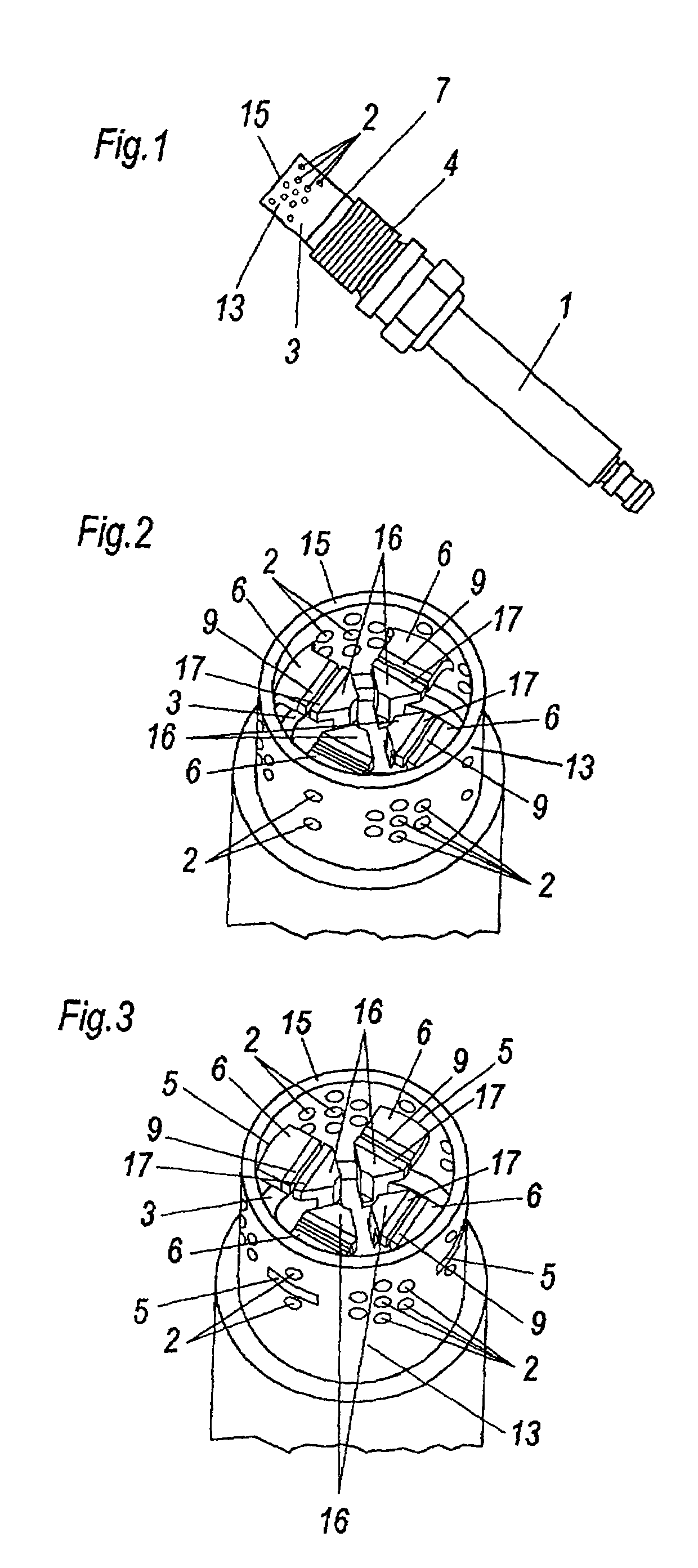
[0021]In the case of the spark plug with swirl chamber 3, as shown in FIG. 1, recourse is made to a standard industry spark plug as is commercially offered by various spark plug manufacturers.

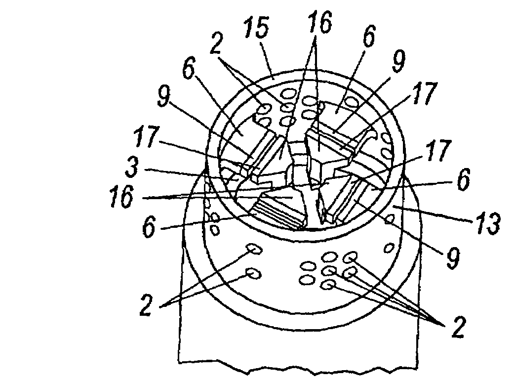
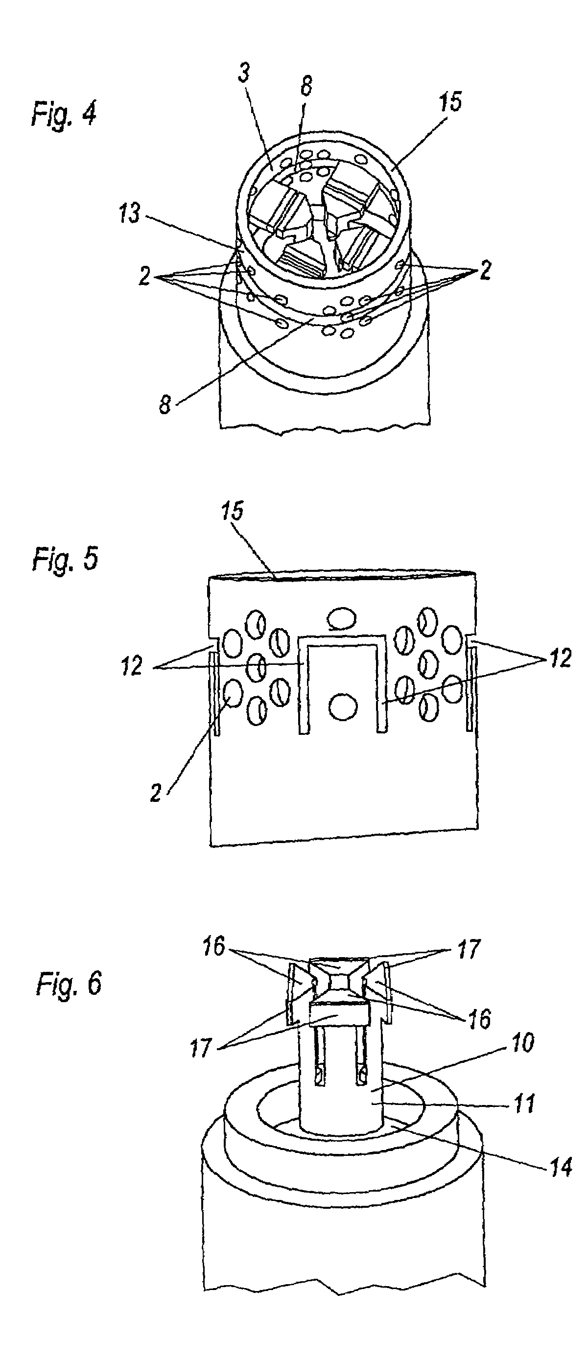
[0022]Mounted to the lower housing portion 1 at the engine side is a swirl chamber 3, with the end 15 thereof that is towards the combustion chamber being open. In the specific case, for reasons of resistance to temperature and hot corrosion, an open swirl chamber 3 with a wall 13 of Inco Alloy 600 (Wno 2.4816) is welded by means of laser at the weld seam 7 to the lower housing portion 4. As alternatives, it is also possible to use other nickel-based alloys or high-temperature high-quality steels for the wall 13. The swirl chamber 3 is alternatively also made in one piece, that is to say as an integral component part of the lower housing portion 4.

[0023]The wall 13 of the swirl chamber 3 has openings 2 which permit good access for the mixture. The openings 2 can be in the form of bores, slots, ...


PUM


Abstract

A spark plug of an internal combustion engine, in particular for use in Otto-cycle gas engines, comprising an insulator body, a base central electrode, at least one ground electrode and at least one swirl chamber, wherein the electrodes of the spark plug are surrounded by a wall, which in particular is in the form of a surface of a cylinder, of the swirl chamber, wherein at least one ground electrode carrier arrangement (8) with a plurality of inwardly facing, preferably flat ground electrodes (9) or a plurality of ground electrode carriers (6) each with inwardly facing, preferably flat ground electrodes (9) is or are arranged at the wall (13) of the swirl chamber (3).

Description

BACKGROUND OF THE INVENTION[0001]The present invention concerns a spark plug of an internal combustion engine, in particular for use in Otto-cycle gas engines, comprising an insulator body, a base central electrode, at least one ground electrode and at least one swirl chamber, wherein the electrodes of the spark plug are surrounded by a wall, which in particular is in the form of a surface of a cylinder, of the swirl chamber. The invention further concerns a process for producing a spark plug.[0002]The spark plugs which are available at the present time for industrial gas engines are in many cases products which were derived from the automobile industry and adapted by suitable improvements for the preferential use in industrial gas engines. Those spark plugs generally have a cylindrical central electrode which is provided with a precious metal pin. In regard to the ground electrodes, both configurations with a hook electrode and also configurations with between two and four laterall...

Claims


Application Information

Patent Timeline
IPC IPC(8): H01T13/20F02P13/00H01T13/32H01T13/38H01T13/46H01T13/54H01T21/02
CPCH01T13/54H01T13/467
Inventor FRANCESCONI, CHRISTIANEGGER, CHRISTOPHKLAUSNER, JOHANNGRUBER, FRIEDRICH
Owner GE JENBACHER
Why Eureka
Try Eureka