Discharge lamp device including an airtight container filled with a noble gas

a discharge lamp and noble gas technology, applied in the direction of discharge tube luminescnet screens, lighting and heating apparatus, instruments, etc., can solve the problems of poor luminous flux startup characteristic, undesirable, and the desire for light source devices without mercury, and achieve the effect of reducing cost, reducing size and improving efficiency

Inactive Publication Date: 2009-11-17
PANASONIC CORP
View PDF28 Cites 0 Cited by
  • Summary
  • Abstract
  • Description
  • Claims
  • Application Information

AI Technical Summary

Benefits of technology

[0014]According to this discharge lamp device, the holder functions as a spacer provided between the airtight container and the second electrode. The holder allows the second electrode to be located at a position having a predetermined distance to the airtight container. This maintains a fixed interval between the second electrode and the airtight container to prevent ozone or the like from being caused between the second electrode and the airtight container. Thus, stable light emission can be provided without dielectric breakdown. Furthermore, the second electrode has the reflective surface. Thus, this discharge lamp device does not require additional reflection plate and thus can have smaller size and reduced cost.
[0029]Furthermore, the second electrode including the reflective surface allows the discharge lamp device to have smaller size and smaller cost. Thus, a liquid crystal display including this discharge lamp device for example also can have smaller size and smaller cost.

Problems solved by technology

However, the above light source device using mercury is highly dependent on a temperature and thus has a poor luminous flux startup characteristic at a low temperature and is not desirable from a viewpoint of environmental protection.
Thus, such a light source device that does not use mercury has been desired.
However, the light source devices introduced by the above publications find difficulty in completely sealing an outer electrode to a glass bulb and thus a small space is caused.
The status as described above not only causes a light source device to emit light in a very unstable manner but also causes air in this small space to induce dielectric breakdown.
This causes a problem where ionized gas molecules (e.g., ozone) for example break the outer electrode or the glass bulb.
Furthermore, even when the light source devices introduced by the above publications are manufactured so that a clearance is prevented from being caused between an outer electrode and a glass bulb by mechanically abutting the outer electrode to the glass bulb or by adhesive agent, an evaporation method, or a sputter technique, the adhesion status therebetween is unstable due to a manufacturing error, vibration during the operation, or an environmental change (e.g., temperature change) for example.

Method used


Image

  • Discharge lamp device including an airtight container filled with a noble gas
  • Discharge lamp device including an airtight container filled with a noble gas
  • Discharge lamp device including an airtight container filled with a noble gas

Examples


embodiment 1

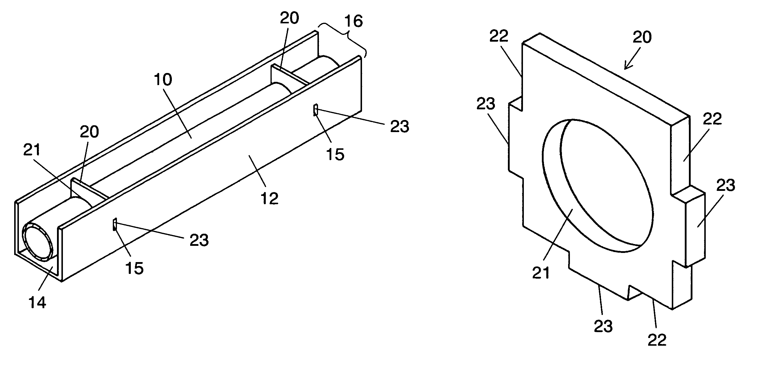
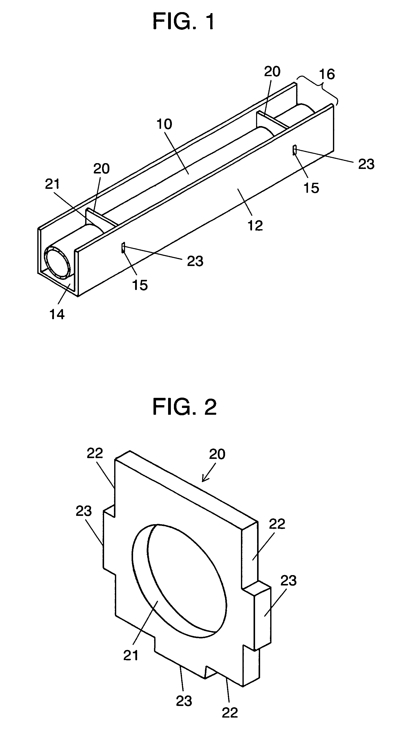
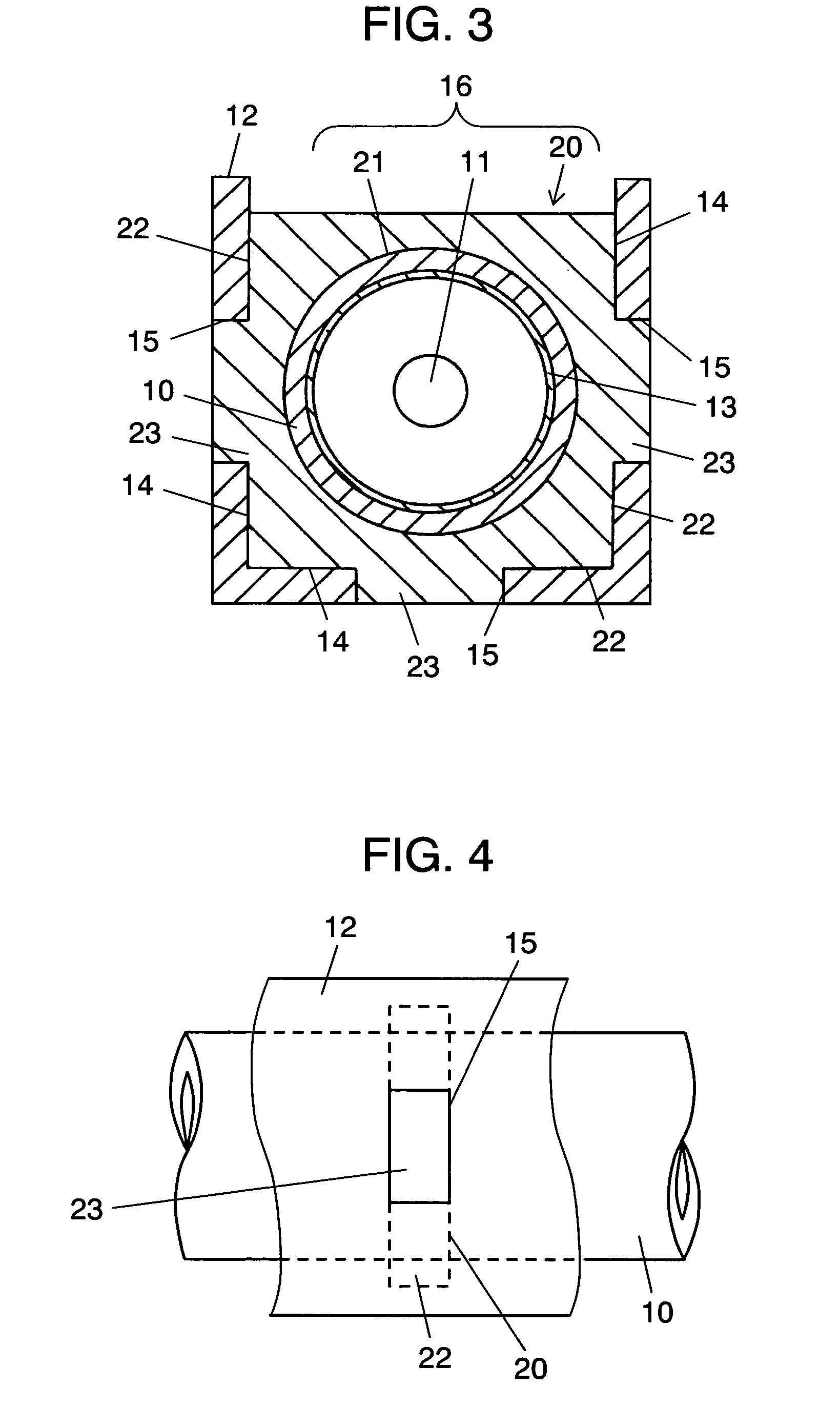
[0056]Embodiment 1 of a discharge lamp device according to the present invention will be described with reference to FIG. 1 to FIG. 6. The discharge lamp device according to Embodiment 1 includes airtight container 10 in which both end sections of a glass bulb (not shown) are sealed. The interior of airtight container 10 is filled with discharge medium mainly including noble gas. One end section or both end sections of airtight container 10 include(s) first electrode 11. Insulating holder 2 is externally attached to airtight container 10 at one or a plurality position(s) of airtight container 10 (two positions in FIG. 1). Holder 20 is attached with second electrode 12.

[0057]Airtight container 10 is made of material such as glass (borosilicate glass, silica glass, soda glass, lead glass), organic matter (e.g., acryl), or other translucent materials. Airtight container 10 basically has a straight pipe-like shape but also may have an L-like shape, a U-like shape, or a rectangular shape...

embodiment 2

[0071]Embodiment 2 will be described with reference to FIG. 7 and FIG. 8. Embodiment 2 is characterized in that a relation between thickness a of holder 20 in a longitudinal direction of airtight container 10 and width b of protrusion 23 in the longitudinal direction of airtight container 10 is determined to be a>b. Specifically, holder 20 has a thickness that is thicker than a width of protrusion 23.

[0072]When a user holds a liquid crystal display using the discharge lamp device of the present invention as a backlight by hands, a risk may be caused where the discharge lamp device receives pressure from a side to deform holder 20 and thus a distance between airtight container 10 and second electrode 12 is changed. Another risk may be caused where dust may come into second electrode 12 via a clearance between protrusion 23 and fitting hole 15 formed in second electrode 12.

[0073]Thus, the structure according to Embodiment 2 can minimize the deformation of holder 20 even when being sub...

embodiment 3

[0074]Embodiment 3 will be described with reference to FIG. 9 and FIG. 10. Embodiment 3 is characterized in that holder 20 is structured as described below. Specifically, length a of holder 20 in the longitudinal direction of airtight container 10 is determined such that a relation between length a1 at a side from which airtight container 10 emits light and length a2 at a side at which second electrode 12 is provided and which is opposed to opening 16 is a12. Specifically, holder 20 is formed to have an almost trapezoidal shape when seen from the front and holder 20 has a thickness that is reduced in a direction along which light is emitted. A relation between a2 and width b of protrusion 23 of holder 20 is determined to be a2>b from the viewpoint of securing the rigidity of holder 20. A relation between a1 and b is determined to be a110.

[0075]The structure as described above provides not only the function and effect of Embodiment 2 but also forms holder 20 so that the thickness of ...


PUM


Abstract

A discharge lamp device is provided that includes a light source device including a reflective surface. In the light source, noble gas not including mercury is excited to provide stable light emission and ozone or the like is prevented from being generated. This discharge lamp device includes airtight container (10) in which both end sections of a glass bulb are sealed. Airtight container (10) is filled with a discharge medium mainly including noble gas. One end section of airtight container (10) includes first electrode (11). Airtight container (10) is externally attached to insulating holder (20) having a square plate-like shape that includes penetration hole(s) (21) at one or a plurality of position(s). Holder (20) is fitted to second electrode (12) shaped to be a U-like groove so that a fixed interval between airtight container (10) and second electrode (12) is maintained. Three side faces (22) of holder (20) include protrusion (23) and second electrode (12) includes fitting hole (15) fitted with protrusion (23). By fitting protrusion (23) with fitting hole (15), holder (20) is prevented from disengaged from second electrode (12).

Description

RELATED APPLICATIONS[0001]This application is the U.S. National Phase under 35 U.S.C. § 371 of International Application No. PCT / JP2005 / 000005, filed on Jan. 5, 2005, which in turn claims the benefit of Japanese Application No. 2004-006596, filed on Jan. 14, 2004, the disclosures of which Applications are incorporated by reference herein.TECHNICAL FIELD[0002]The present invention relates to a discharge lamp device that includes a light source device having an airtight container filled with a discharge medium, a pair of electrodes or the like and a reflective surface. In particular, the present invention relates to a discharge lamp device in which an airtight container is filled with noble gas not including mercury.BACKGROUND ART[0003]A backlight used for a liquid crystal display for example is composed of a light guide plate, a discharge lamp device or the like and the discharge lamp device is composed of a light source device and a reflection member. A conventional light source dev...

Claims


Application Information

Patent Timeline
Patent Type & Authority Patents(United States)
IPC IPC(8): H01J11/00H01J61/30H01J65/00
CPCH01J5/54H01J65/046H01J65/00H01J5/60
Inventor HIROHASHI, MASAKISHIMIZU, NOBUHIROYAMAMOTO, NORIKAZUSHIGETA, TERUAKIMATSUBAYASHI, YOKOWAKIMURA, YUTAKAFURUKAWA, SHUUJIDEJIMA, HISASHI
Owner PANASONIC CORP
Why Eureka
Try Eureka