Sequentially addressable radius measurements of an optical surface using a range finder

Active Publication Date: 2009-11-17
HARRIS CORP
View PDF8 Cites 8 Cited by
  • Summary
  • Abstract
  • Description
  • Claims
  • Application Information

AI Technical Summary

Benefits of technology

[0018]A tip-tilt mirror is disposed between the range finder and the ring mirror for aligning an interferometer beam with the transmitted beam of the range finder. Folding mirrors are included for intercepting the transmitted beam of the range finder and lengthening the distance between the range finder and the optical surface.

Problems solved by technology

If an instrument, external to the center of curvature of the PMSA, is used to measure the radius of curvature, there are limitations in creating reference features that may be viewed from the instrument.
This limitation pushes the measurement towards a solution that incorporates the instrument into a region near the center of curvature.
Fabricating a long spacer rod becomes impractical as the spacing between the PM and the center of curvature null increases.
In addition, a spacer rod presents risk to the optical components since the PM is often located below the spacer rod.
The spacer rod tip may cause damage to the coating or glass as it contacts the PM surface.
Disadvantageously, the PTE needs power and cooling lines.
In addition, if the laser finders are mounted on different isolation platforms they become subject to vibration errors.
There is also uncertainty associated with the placement of the corner cubes and the CMM measurements of the corner cubes relative to the mirror.
Additionally, when a PM is measured while mounted in a telescope, the center hole is typically inaccessible and not visible from the location of the interferometer / null.
Use of the center-hole fixture with three spherical feet is only effective when used with a monolithic PM.

Method used


Image

  • Sequentially addressable radius measurements of an optical surface using a range finder
  • Sequentially addressable radius measurements of an optical surface using a range finder
  • Sequentially addressable radius measurements of an optical surface using a range finder

Examples


Embodiment Construction

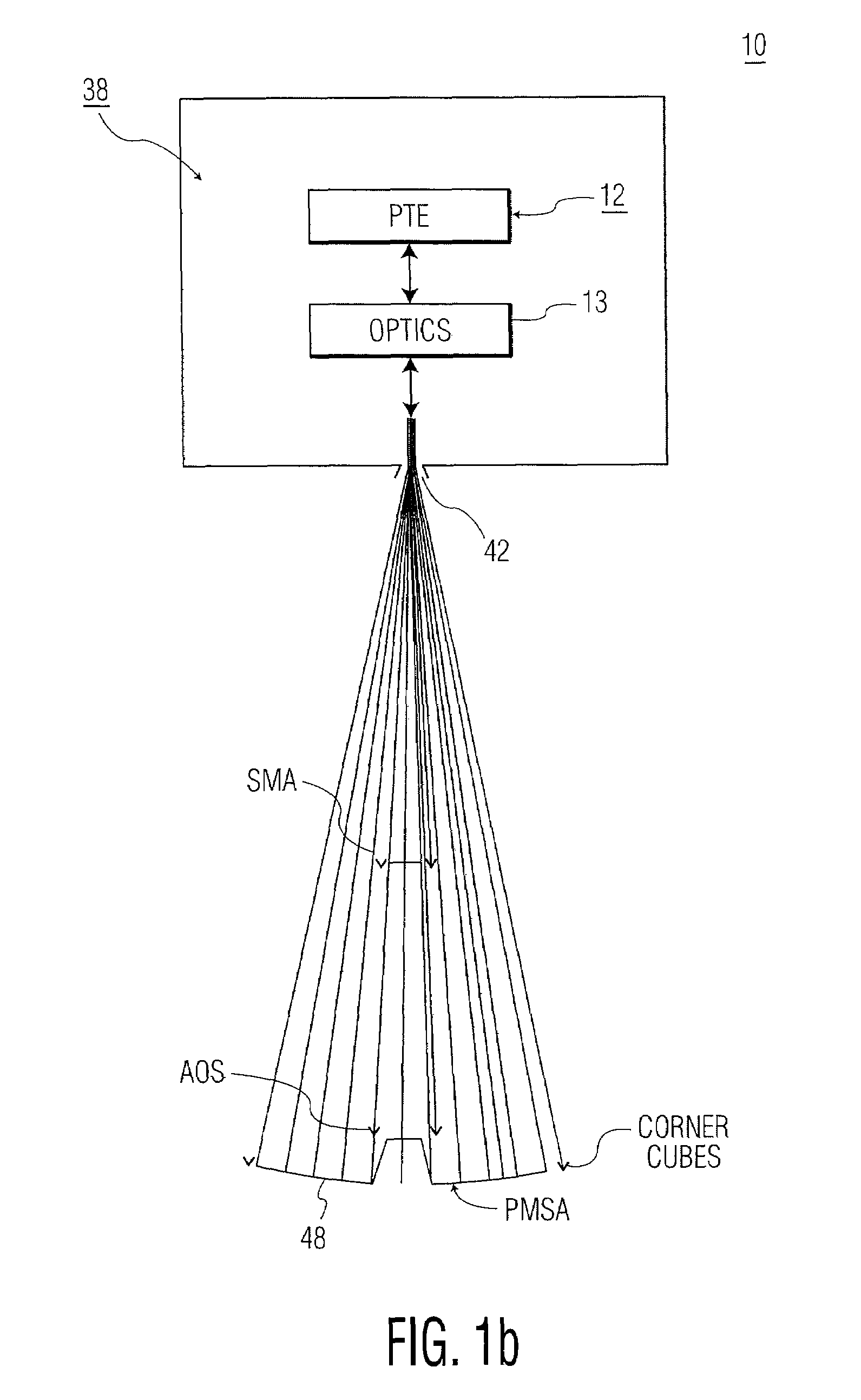
[0029]As will be explained, the present invention provides a series of absolute distance measurements to one or more mirror segments of a PM and quickly determines the RoCs of each mirror segment.

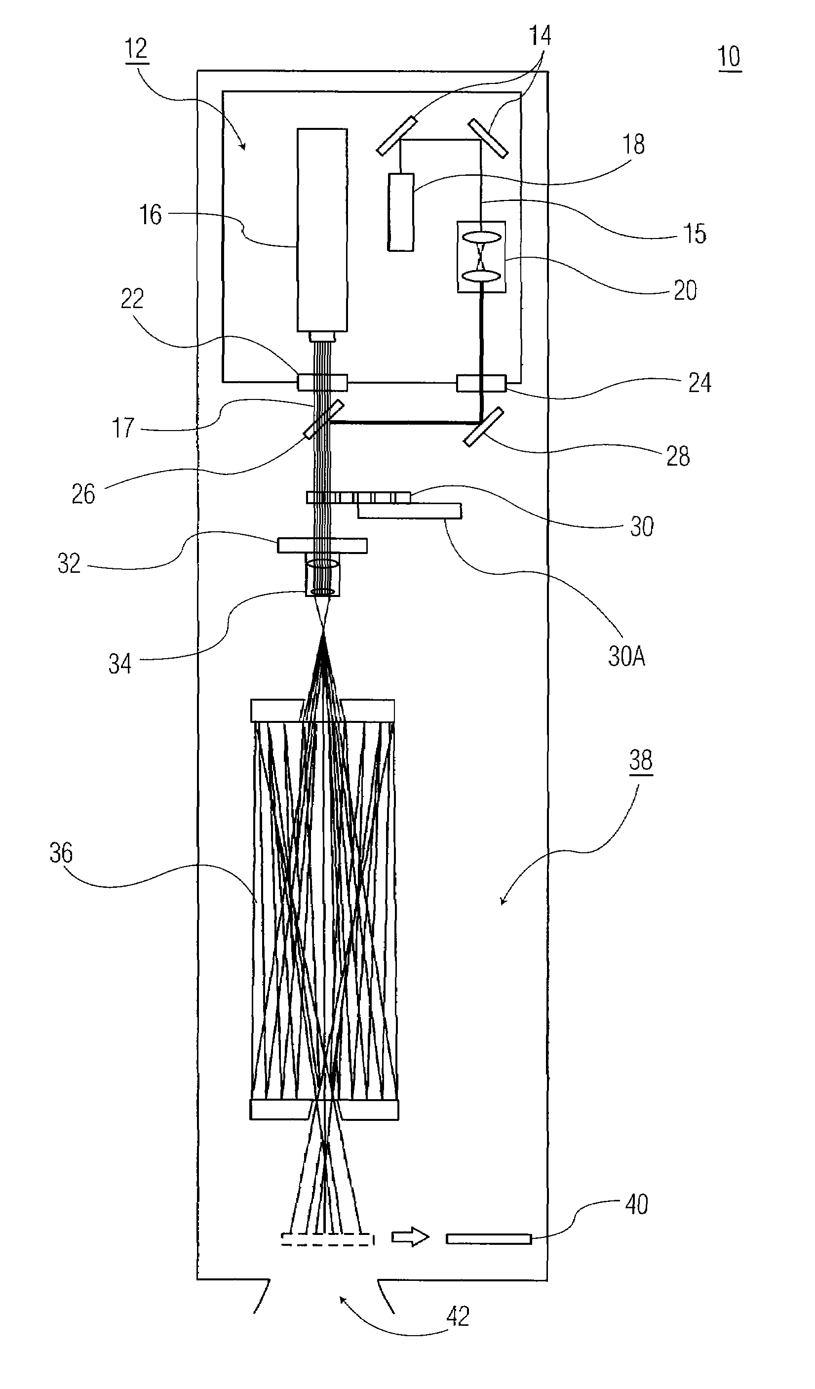
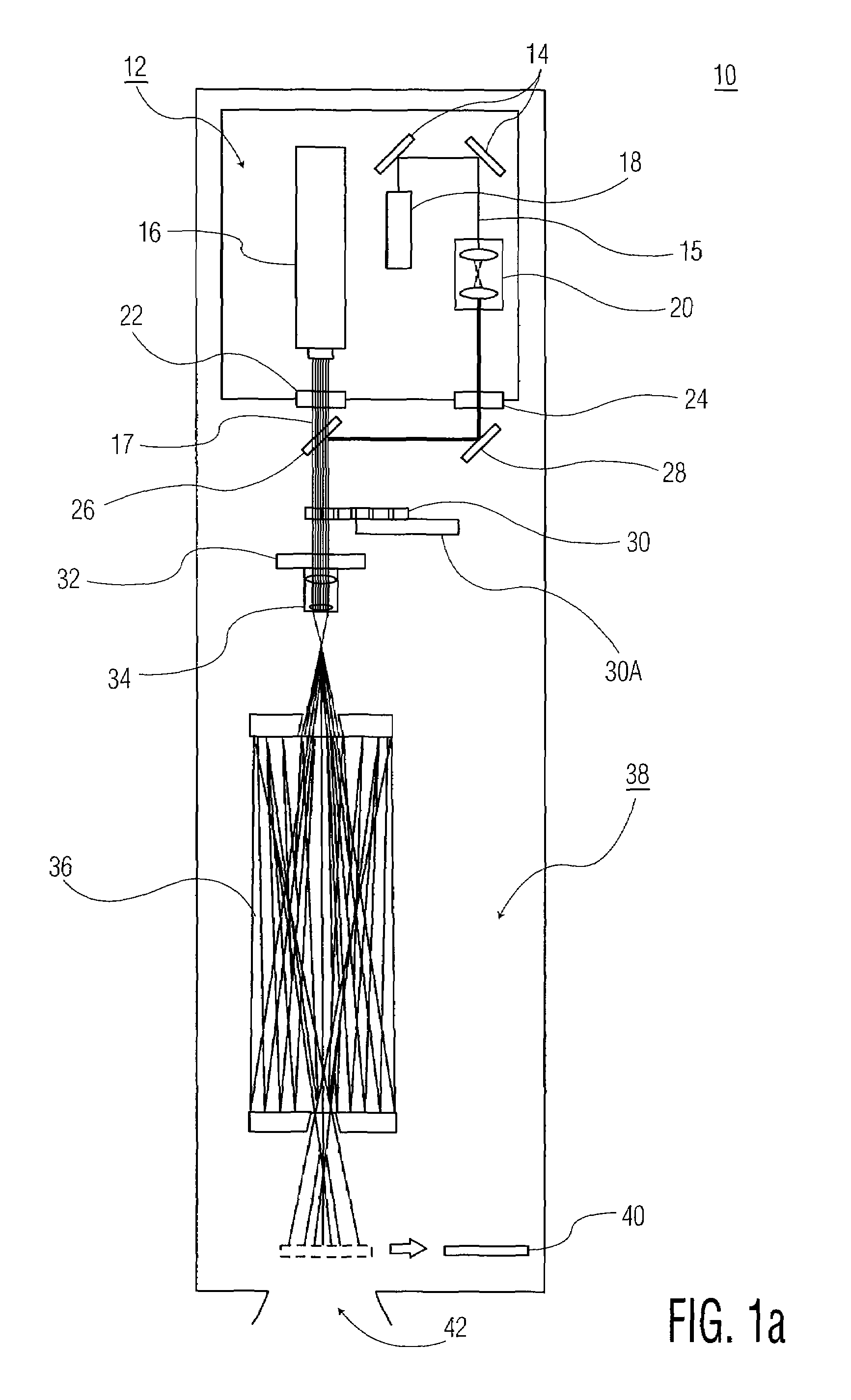
[0030]As will be explained, the present invention takes advantage of unique geometric properties of an achromatic objective and a reflective null assembly to direct a range finder's beam at normal incidence to the PM surface. This permits multiple sequential radius measurements on any mirror segment of a PM.

[0031]The present invention includes a single range finder, multiple fold mirrors, a collimator, mask apertures, scanning pentaprisms, and a reflective null assembly. An example of a ranger finder that may be used by the present invention is an absolute distance meter (ADM) manufactured by Leica. The ADM transmits a 10 mm diameter beam at a wavelength of 780 nm; has a range of 50 meters; and an accuracy of 20 microns in a vacuum environment. The ADM exemplified below is typically used in...


PUM


Abstract

A system for measuring distance to an optical surface includes a range finder for transmitting a beam toward the optical surface, and a ring mirror disposed between the range finder and the optical surface. The ring mirror has (a) a circumferential reflecting surface for reflecting a portion of the transmitted beam back to the range finder, and (b) a central aperture for passing another portion of the transmitted beam toward the optical surface. The circumferential reflecting surface is effective in providing a zero reference point for the range finder. The central aperture is effective in passing the transmitted beam to the optical surface for sequentially addressing the optical surface at different locations on the optical surface. The transmitted beam may be steerable for (a) providing the zero reference point circumferentially about the reflecting surface, and (b) providing sequential addresses to locations on the optical surface.

Description

[0001]This application claims priority of U.S. Provisional Application Ser. No. 60 / 992,200, filed on Dec. 4, 2007.TECHNICAL FIELD[0002]The present invention relates, in general, to the field of optics. More specifically, the present invention relates to systems and methods for testing and aligning optical surfaces, such as primary mirror segment assemblies (PMSAs) of a primary mirror (PM) of a telescope.BACKGROUND OF THE INVENTION[0003]Metrology devices are known to measure spatial coordinates of an object under test. Examples of metrology devices include laser rangefinders, laser range scanners, photogrammetry cameras, theodolites and electronic autocollimators. For example, a laser rangefinder typically determines the spatial coordinates of an object under test based on a laser beam reflected from points on the object under test. The laser rangefinder generally measures the distance to the object under test by computing a time of arrival of a transmitted pulsed laser beam.[0004]Me...

Claims


Application Information

Patent Timeline
IPC IPC(8): G01C3/08
CPCG01C3/08
Inventor HAYDEN, JOSEPH E.MERLE, CORMIC K.WICK, ERIC L.
Owner HARRIS CORP
Why Eureka
Try Eureka