Solid electrolytic capacitor and method of manufacturing the same

a technology of electrolytic capacitor and solid electrolytic capacitor, which is applied in the direction of fixed capacitor details, casings/cabinets/drawers, electrical apparatus casings/cabinets/drawers, etc., can solve the problems of product quality degradation, defect, manufacturing cost increase, etc., to reduce manufacturing cost, simplify structure, and reduce size

Active Publication Date: 2009-11-17
SAMSUNG ELECTRO MECHANICS CO LTD
View PDF7 Cites 9 Cited by
  • Summary
  • Abstract
  • Description
  • Claims
  • Application Information

AI Technical Summary

Benefits of technology

[0016]An advantage of the present invention is that it provides a solid electrolytic capacitor and a method of manufacturing the same, which can reduce a manufacturing cost by simplifying a structure and a manufacturing process, can achieve a reduction in size, can maximize capacitance, and can implement a low ESR (Equivalent Series Resistance) characteristic.
[0017]Additional aspects and advantages of the present general inventive concept will be set forth in part in the description which follows and, in part, will be obvious from the description, or may be learned by practice of the general inventive concept.
[0018]According to an aspect of the invention, a solid electrolytic capacitor comprises a capacitor element with a positive polarity; an anode wire inserted and connected to a lower portion of the capacitor element; a cathode extraction layer formed on the capacitor element; an anode lead frame provided on one side of the lower surface of the capacitor element so as to be electrically insulated from the cathode extraction layer, the anode lead frame having an insertion portion into which a projecting lower portion of the anode wire is inserted; a cathode lead frame provided on the other side of the lower surface of the capacitor element so as to be electrically connected to the cathode extraction layer; a molding portion formed to surround the capacitor element and exposing the lower end surface of the anode wire, the lower surface of the anode lead frame, and the lower surface of the cathode lead frame; an anode lead terminal provided on the molding portion so as to be electrically connected to the lower end surface of the anode wire and the lower surface of the anode lead frame; and a cathode lead terminal provided on the molding portion so as to be electrically connected to the lower surface of the cathode lead frame.
[0019]Preferably, the anode lead frame is bonded to the capacitor element through an insulating adhesive, and the cathode lead frame is bonded to the capacitor element through a conductive adhesive.
[0020]The anode and cathode lead frames may be formed of a conductive material.
[0021]The insertion portion of the anode lead frame may be formed in a hole shape or a groove shape which is opened toward the cathode lead frame.

Problems solved by technology

Further, dielectrics are destroyed by the heat shock applied to the capacitor element 11 such that a product quality is degraded and defects occur.
Therefore, a manufacturing cost increases.

Method used


Image

  • Solid electrolytic capacitor and method of manufacturing the same
  • Solid electrolytic capacitor and method of manufacturing the same
  • Solid electrolytic capacitor and method of manufacturing the same

Examples


first embodiment

of Solid Electrolytic Capacitor

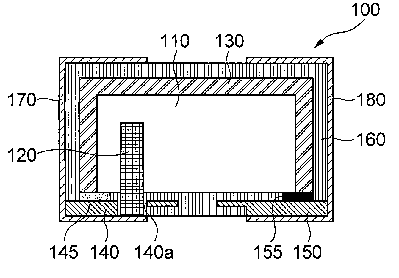
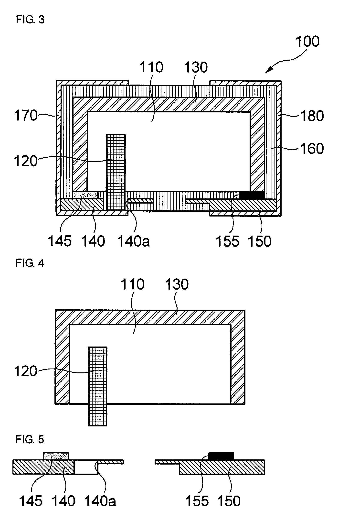
[0049]Referring to FIG. 3, a solid electrolytic capacitor according to a first embodiment of the invention will be described in detail.

[0050]FIG. 3 is a front cross-sectional view of a solid electrolytic capacitor according to the first embodiment of the invention.

[0051]As shown in FIG. 3, the solid electrolytic capacitor 100 according to the first embodiment of the invention includes a capacitor element 110 with a positive polarity; an anode wire 120 which is inserted and connected to a lower portion of the capacitor element 110; a cathode extraction layer 130 formed on the capacitor element 110; an anode lead frame 140 which is provided on one side of the lower surface of the capacitor element 110 so as to be electrically insulated from the cathode extraction layer 130 and has an insertion portion 140a into which a projecting lower portion of the anode wire 120 is inserted; a cathode lead frame 150 which is provided on the other side of the lower sur...

second embodiment

of Solid Electrolytic Capacitor

[0088]Referring to FIGS. 11 and 12, a solid electrolytic capacitor according to a second embodiment of the invention will be described in detail.

[0089]FIG. 11 is a front cross-sectional view of a solid electrolytic capacitor according to a second embodiment of the invention. FIG. 12 is a bottom view of the solid electrolytic capacitor of FIG. 11, showing a state where anode and cathode lead terminals are removed.

[0090]As shown in FIG. 11, the solid electrolytic capacitor 200 according to the second embodiment of the invention includes a capacitor element 210, an anode wire 220, a cathode extraction layer 230, an anode lead frame 240, a cathode lead frame 250, a molding portion 260, an anode lead terminal 270, and a cathode lead terminal 280, similar to the first embodiment.

[0091]As shown in FIG. 12, an insertion portion 240a formed in the anode lead frame 240 of the solid electrolytic capacitor 200 according to the second embodiment of the invention ha...

third embodiment

of Solid Electrolytic Capacitor

[0094]Referring to FIGS. 13 and 14, a solid electrolytic capacitor according to a third embodiment of the invention will be described in detail.

[0095]FIG. 13 is a front cross-sectional view of a solid electrolytic capacitor according to a third embodiment of the invention. FIG. 14 is a bottom view of the solid electrolytic capacitor of FIG. 13, showing a state where anode and cathode lead terminals are removed.

[0096]As shown in FIG. 13, the solid electrolytic capacitor 300 according to the third embodiment of the invention includes a capacitor element 310, an anode wire 320, a cathode extraction layer 330, an anode lead frame 340, a cathode lead frame 350, a molding portion 360, an anode lead terminal 370, and a cathode lead terminal 380, similar to the first embodiment.

[0097]As shown in FIGS. 13 and 14, the anode wire 320 of the solid electrolytic capacitor 300 is inserted and connected to a lower portion of the capacitor element 310 so as to be posit...


PUM

PropertyMeasurementUnit
thicknessaaaaaaaaaa
temperatureaaaaaaaaaa

Abstract

Provided is a solid electrolytic capacitor including a capacitor element with a positive polarity; an anode wire inserted and connected to a lower portion of the capacitor element; a cathode extraction layer formed on the capacitor element; an anode lead frame provided on one side of the lower surface of the capacitor element so as to be electrically insulated from the cathode extraction layer, the anode lead frame having an insertion portion into which a projecting lower portion of the anode wire is inserted; a cathode lead frame provided on the other side of the lower surface of the capacitor element so as to be electrically connected to the cathode extraction layer; a molding portion formed to surround the capacitor element and exposing the lower end surface of the anode wire, the lower surface of the anode lead frame, and the lower surface of the cathode lead frame; an anode lead terminal provided on the molding portion so as to be electrically connected to the lower end surface of the anode wire and the lower surface of the anode lead frame; and a cathode lead terminal provided on the molding portion so as to be electrically connected to the lower surface of the cathode lead frame.

Description

CROSS-REFERENCE TO RELATED APPLICATIONS[0001]This application claims the benefit of Korean Patent Application No. 10-2007-0132564 filed with the Korea Intellectual Property Office on Dec. 17, 2007, the disclosure of which is incorporated herein by reference.BACKGROUND OF THE INVENTION[0002]1. Field of the Invention[0003]The present invention relates to a solid electrolytic capacitor and a method of manufacturing the same.[0004]2. Description of the Related Art[0005]In general, solid electrolytic capacitors having a function of storing electricity are electronic components used for blocking direct currents and passing alternating currents. Among the solid electrolytic capacitors, the most representative one is a tantalum capacitor which is used in application circuits, of which the rate voltage range is low, as well as general industrial equipments. In particular, the tantalum capacitor is frequently used in circuits requiring an excellent frequency characteristic or for reducing noi...

Claims


Application Information

Patent Timeline
Patent Type & Authority Patents(United States)
IPC IPC(8): H01G4/228H01G9/00
CPCH01G9/012H01G9/10H01G2/065H01G9/15Y10T29/417
Inventor CHOI, HEE SUNGLEE, SEOUNG JAELEE, YEOUNG JINWON, SUNG HANJUNG, HA YONGSHIN, HYUN HOPARK, JUNG TAEJEONG, JAE YOUN
Owner SAMSUNG ELECTRO MECHANICS CO LTD
Why Eureka
Try Eureka