
Controlling and operating technical processes

a technology of operating and controlling technical processes, applied in the direction of automatic controllers, program control, specific program execution arrangements, etc., can solve the problems of inconsistentness, inability to adapt to the differentiation requirements of distinct processes, and difficulty in achieving the effect of achieving the effect of achieving the effect of achieving the effect of achieving the effect of achieving the effect of achieving the effect of achieving the effect of achieving the effect of achieving the effect of achieving the effect of achieving the effect o

Active Publication Date: 2009-11-17
RENNER PETER
View PDF27 Cites 10 Cited by
  • Summary
  • Abstract
  • Description
  • Claims
  • Application Information

AI Technical Summary

Benefits of technology

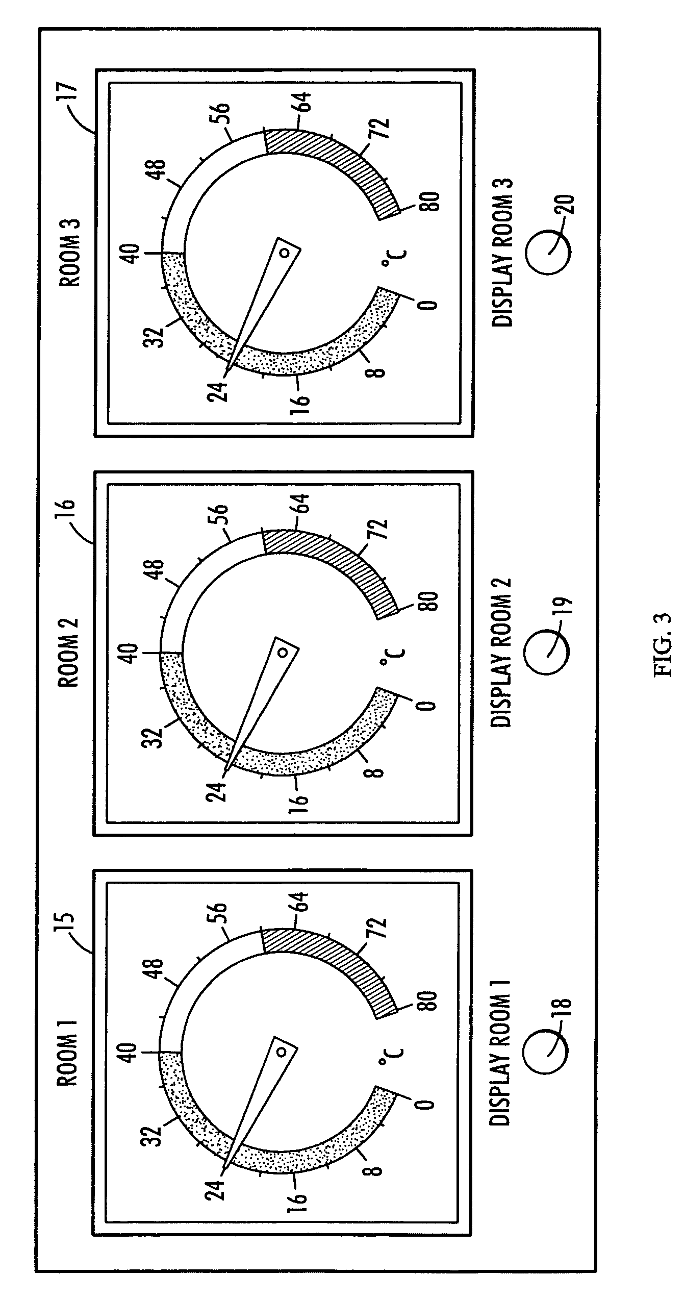
[0018]Distinct graphical symbols are assigned to the various module types. These graphical symbols are clearly distinguishable from one another. In the operating and observation component, which can contain a number of screens, module diagrams are provided. A user creates module diagrams in configuration mode. In this way, a very good overview of the process sequences is advantageously made possible. The control modules are placed as graphical symbols in the module diagram and linked with lines. These lines show symbolically how control modules are invoked by other control modules and can themselves invoke other control modules. The arrangement of the symbols and the linking lines, which are subject to set rules, make it possible to identify at a glance the structure and the sequences of the automation task. According to the invention, the control modules whose program contents are currently being carried out are highlighted in runtime mode, that is, during the execution of a process. In this way an observer can identify in what stage the process sequence is.

Problems solved by technology

Control software and visualization do not fit together because they are different in concept, relate to different platforms, so that these approaches are not consistent.
This manifests itself in an inadequate adaptation to the differentiated requirements of the distinct processes.
In practice, this often leads to problems and complicated approaches.
Automatic control, however, was not possible in this way.
In the opinion of many users, the institution of automation on the basis of such approaches is very complicated and demands a long familiarization time.
Consistency between operating and observing and automation was not achieved with these approaches.

Method used


Image

  • Controlling and operating technical processes
  • Controlling and operating technical processes
  • Controlling and operating technical processes

Examples


Embodiment Construction

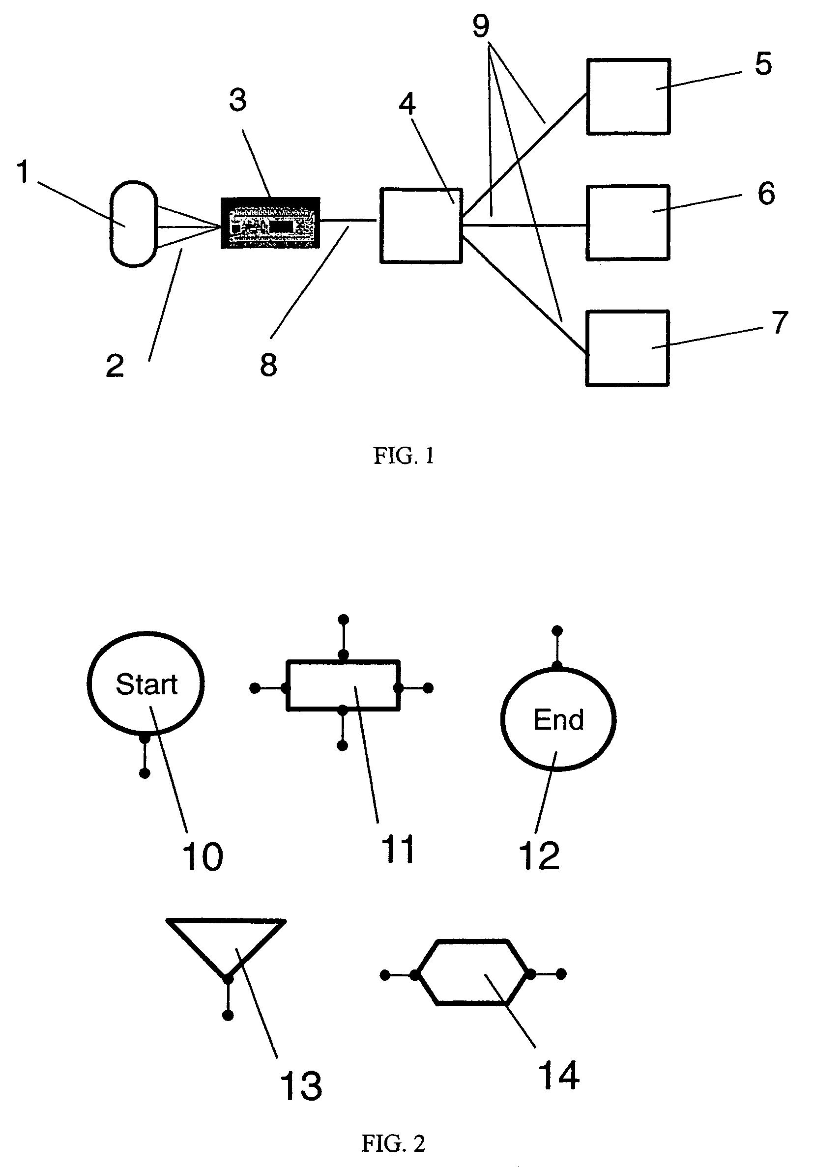
[0036]The reference characters in FIG. 1 have the following meanings:[0037]1: a process to be controlled;[0038]2: sensor and actuator lines, which link the sensors and actuators of the process with the measurement and control units;[0039]3: a measurement and control unit;[0040]4: a control program;[0041]5: an operating and observation component;[0042]6: a database;[0043]7: a printer for creating reports;[0044]8: a data channel; and[0045]9: data channels.

[0046]Process 1 of FIG. 1 is linked to a measurement and control unit 3 via measurement and control lines 2. The measurement and control lines 2 transport signals of the sensors of process 1 to a measurement and control unit 3 and transport control signals in the reversed sense to the actuators of process 1. The measurement and control unit 3 is both a measuring instrument and a data-processing device. It makes certain that the process signals are transformed in such fashion that the data can be exchanged with a control program 4 via...


PUM


Abstract

A system for operating and controlling technical processes having at least one component fashioned as a measuring instrument and a control device, which is connected by electrical lines to sensor and actuators of processes, and having a control program, a measurement and control unit, an operating and observation component, optionally a database, optionally a process printer and further components of a process automation, as appropriate, which are connected to one another via data channels and a control program.

Description

BACKGROUND OF THE INVENTION[0001]The invention relates to a method of operating and controlling technical processes. A large group of products, used chiefly for controlling machines, is generally known. They are known as stored-program controllers or programmable logic controllers (PLCs). These devices are equipped with governing control programs that have the task of controlling machines and installations (processes) through sensors and actuators. Visualization software independent of the control software is employed for operator guidance. Control software and visualization do not fit together because they are different in concept, relate to different platforms, so that these approaches are not consistent. This manifests itself in an inadequate adaptation to the differentiated requirements of the distinct processes. In practice, this often leads to problems and complicated approaches.[0002]There is further known a group of products that are employed primarily in research and develo...

Claims


Application Information

Patent Timeline
Patent Type & Authority Patents(United States)
IPC IPC(8): G05B11/01G05B15/00G06F13/00G06F19/00G06F9/44G06F15/173G01F17/00G01F23/00G05B19/418
CPCG05B19/4185G05B2219/31156G05B2219/32404G05B2219/32128G05B2219/31392Y02P90/02
Inventor RENNER, PETER
Owner RENNER PETER
Learn More