
Internal combustion engine and control method thereof

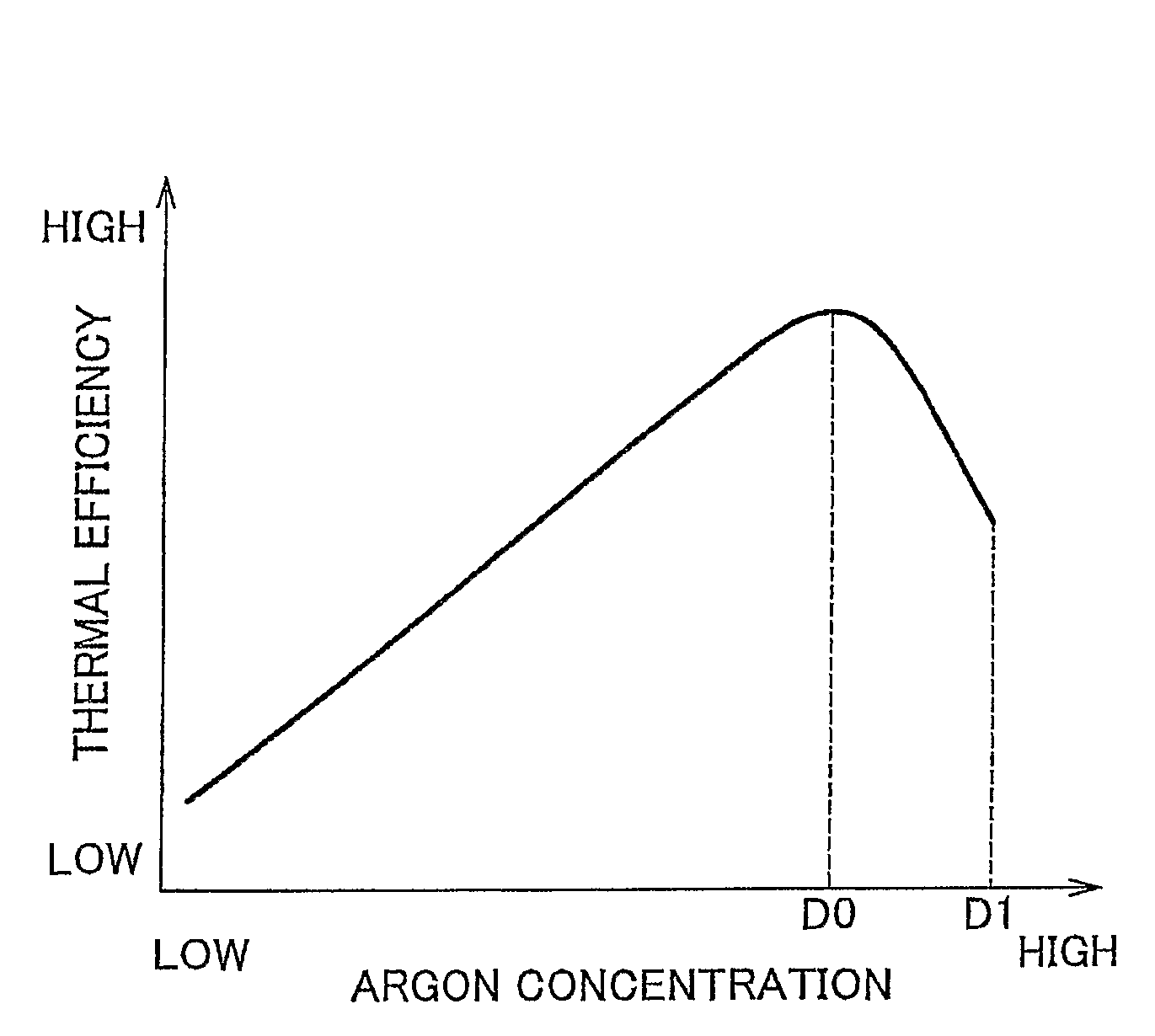
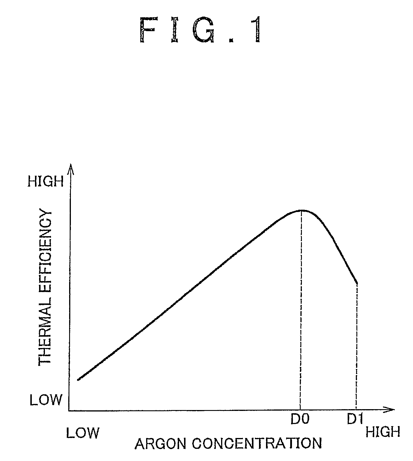
a technology of internal combustion engine and control method, which is applied in the direction of electrical control, process and machine control, instruments, etc., can solve the problems of constant ratio of argon to oxygen supplied to the combustion chamber, decreased so as to achieve good combustion state, improve thermal efficiency of the internal combustion engine, and maintain high value

Inactive Publication Date: 2009-11-24
TOYOTA JIDOSHA KK
View PDF12 Cites 12 Cited by
  • Summary
  • Abstract
  • Description
  • Claims
  • Application Information

AI Technical Summary

Benefits of technology

The invention relates to an operating gas circulation type internal combustion engine that generates power by combusting hydrogen in the combustion chamber and expanding it using heat generated by combusting oxygen. The engine includes hydrogen and oxygen supplying means and operating gas amount regulating means. The hydrogen supplying means determines the amount of hydrogen needed for the engine to generate torque and supplies it to the combustion chamber. The oxygen supplying means determines the amount of oxygen needed for the engine to generate torque and supplies it to the combustion chamber. The operating gas amount regulating means determines the amount of operating gas needed for the engine to generate torque and supplies it to the combustion chamber. By controlling the amounts of hydrogen, oxygen, and operating gas, the engine can generate the necessary torque while maintaining good combustion state. The combustion state index value indicates the combustion state of the engine and can be used to optimize engine performance.

Problems solved by technology

Also, in the range in which the argon concentration is higher than the value D0 it is estimated that the thermal efficiency decreases because combustion becomes unstable due to the relative decrease in the oxygen concentration in the mixed gas the greater the argon concentration.
However, the internal combustion engine described above only keeps the ratio of argon to oxygen supplied to the combustion chamber constant regardless of the required torque.
As a result, the thermal efficiency of the internal combustion engine may decrease due to the argon concentration becoming too low, or due to combustion becoming unstable from the argon concentration becoming too high.

Method used


Image

  • Internal combustion engine and control method thereof
  • Internal combustion engine and control method thereof
  • Internal combustion engine and control method thereof

Examples


Embodiment Construction

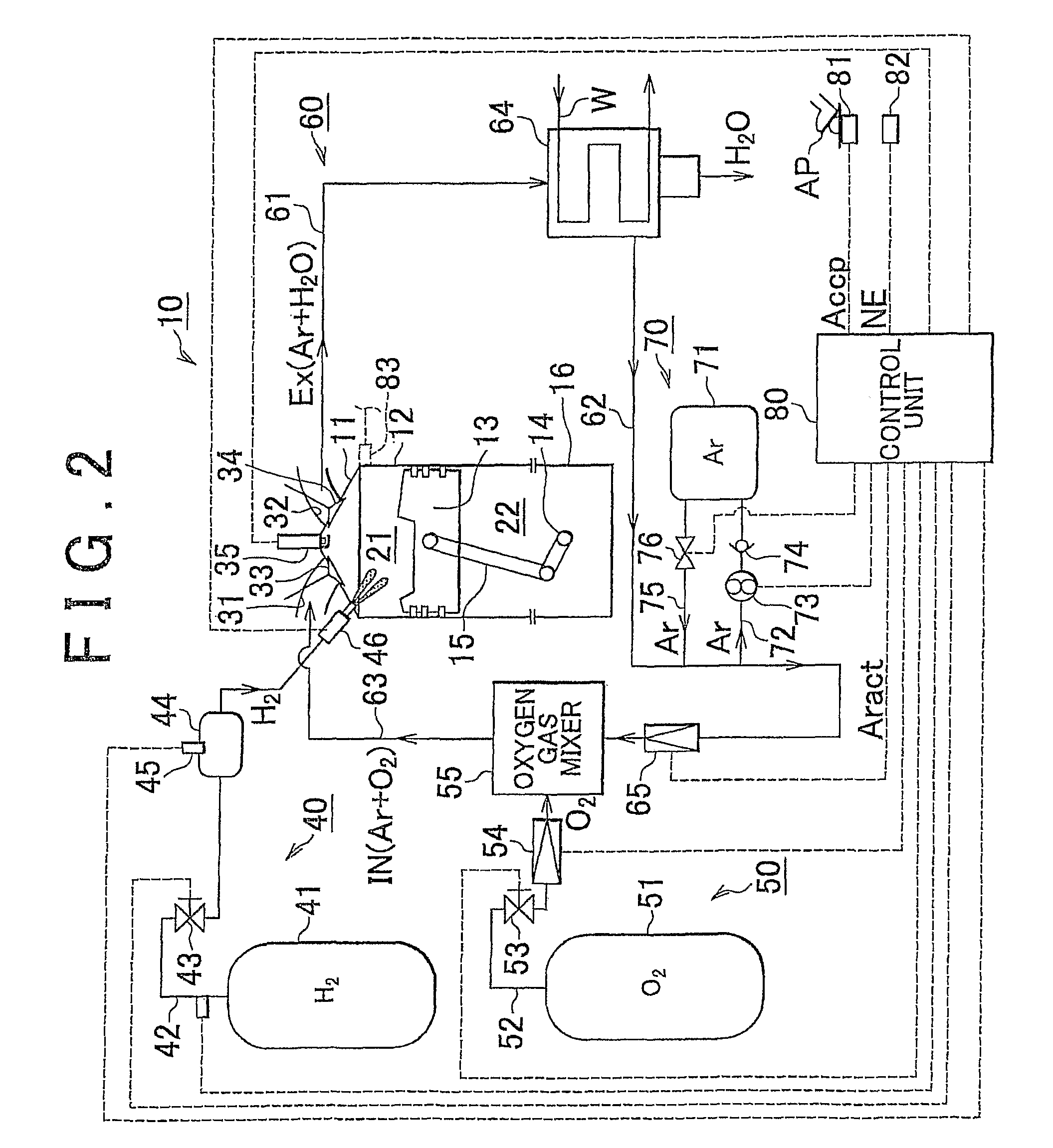
[0042]Hereinafter, example embodiments of an internal combustion engine (i.e., a multiple cylinder internal combustion engine) according to the invention will be described with reference to the accompanying drawings. FIG. 2 is a block diagram schematically showing an internal combustion engine 10 according to a first example embodiment of the invention. Although only a cross-section of a specific cylinder of the internal combustion engine 10 is shown in FIG. 2, the other cylinders have the same structure. This internal combustion engine 10 is an operating gas circulation type internal combustion engine (i.e., a hydrogen-burning closed cycle engine) which generates power by combusting hydrogen in a combustion chamber and expanding operating gas which is an inert gas using heat generated from the combustion, and then supplies the operating gas in the post-combustion gas that, was discharged from the combustion chamber into the combustion chamber again.

[0043]The operating gas is an ine...


PUM


Abstract

An operating gas circulation type internal combustion engine that uses argon as the operating gas, for example, and includes a hydrogen and oxygen supply portion, an argon supply amount regulating portion, and an electric control unit. The electric control unit determines the amount of hydrogen and oxygen to be supplied to a combustion chamber based on a required torque, which is the torque required of the internal combustion engine, and supplies the determined amounts of hydrogen and oxygen to the combustion chamber using the hydrogen supply portion and the oxygen supply portion. Further, the electric control unit determines an amount of operating gas to be supplied to the combustion chamber according to the required torque, and controls the argon supply amount regulating portion such that the determined amount of operating gas is supplied to the combustion chamber.

Description

FIELD OF THE INVENTION[0001]The invention relates to an operating gas circulation type internal combustion engine (i.e., a closed cycle engine) which combusts hydrogen in a combustion chamber, generates power by expanding an operating gas using heat generated by that combustion, and supplies operating gas in post-combustion gas that has been discharged from the combustion chamber into the combustion chamber again. The invention also relates to a control method of that internal combustion engine.BACKGROUND OF THE INVENTION[0002]An operating gas circulation type internal combustion engine is known which uses an inert gas such as argon as the operating gas (i.e., heat medium), combusts hydrogen in a combustion chamber, condenses water vapor in the exhaust gas and discharges it outside the system, and supplies the exhaust gas from which the water vapor was removed (i.e., the inert gas) to the combustion chamber again. Japanese Patent Application Publication No. JP-A-11-93681 describes a...

Claims


Application Information

Patent Timeline
Patent Type & Authority Patents(United States)
IPC IPC(8): F02B43/12
CPCF02D41/0027F02D35/023F02M25/00F02B23/101F02B43/12F02M21/0206F02D19/024F02D2250/18Y02T10/125Y02T10/32F02M21/0245F02M21/0275F02D19/027F02D41/1498F02D2041/147Y02T10/12Y02T10/30
Inventor MITANI, SHINICHISAWADA, DAISAKU
Owner TOYOTA JIDOSHA KK
Learn More