Microfluidic analysis system

a microfluidic and analysis system technology, applied in the direction of positive displacement liquid engines, laboratory glassware, instruments, etc., can solve problems such as the risk of sample contamination by surfaces

Active Publication Date: 2009-11-24
STOKES BIO LTD
View PDF7 Cites 80 Cited by
  • Summary
  • Abstract
  • Description
  • Claims
  • Application Information

AI Technical Summary

Benefits of technology

[0018]In one embodiment, contact between the sample and the vortex chamber surface is avoided by wrapping the sample in an initial carrier fluid within the chamber.

Problems solved by technology

However, this apparently involves a risk of sample contamination by surfaces in the temperature zones and other channels.

Method used


Image

  • Microfluidic analysis system
  • Microfluidic analysis system
  • Microfluidic analysis system

Examples


Embodiment Construction

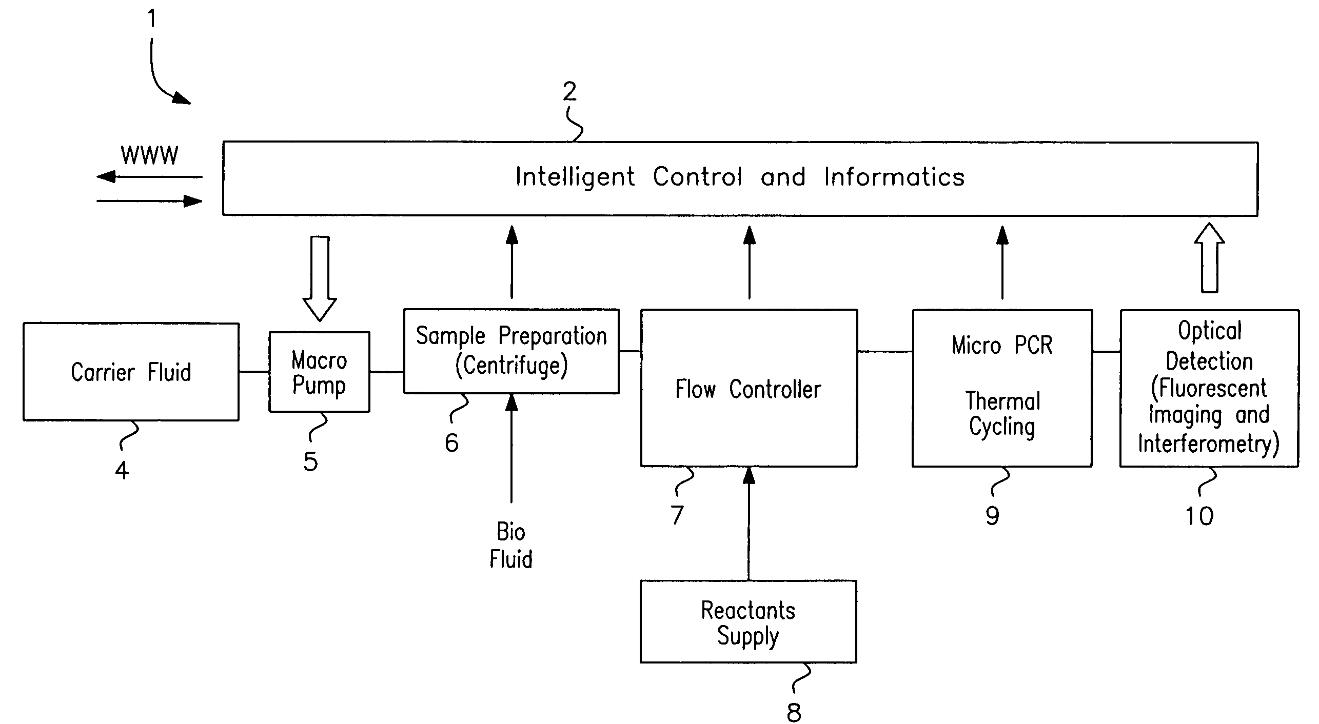
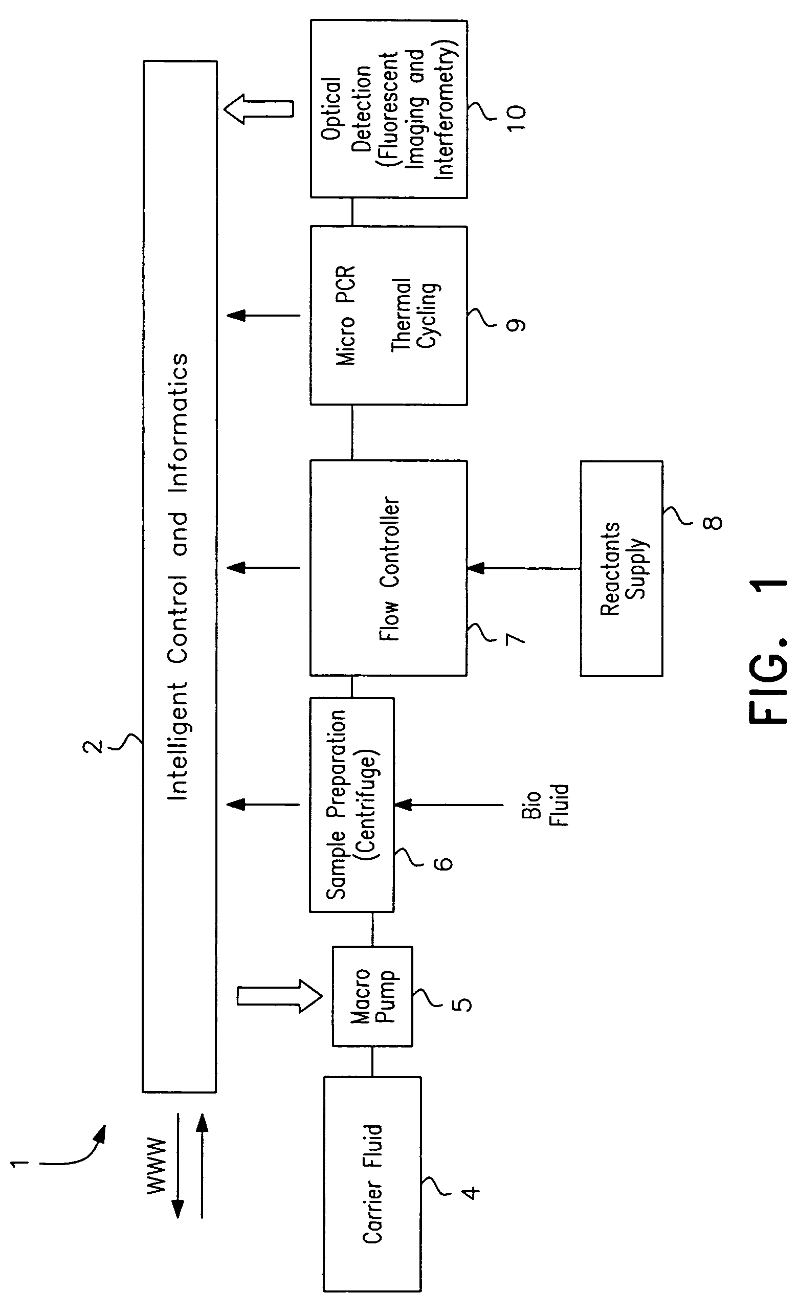
[0042]Referring to FIG. 1 an analysis system 1 comprises a controller 2 which interfaces with various stages. A carrier fluid supply 4 delivers carrier fluid to a macro pump 5 which delivers it at a high flowrate to a sample preparation stage 6. The latter also receives a bio-fluid sample, and centrifuges the sample in a vortex created by carrier fluid flow, as described in more detail below. Reactants are supplied by a supply 8 to a flow controller 7 which delivers streams of separated DNA with reactants enveloped in carrier fluid to a thermal cycling stage 9. The DNA is amplified in the stage 9 and optically detected by a detection stage 10. Throughout the process the samples are enveloped in a biologically non-reactive carrier fluid such as silicone oil. This avoids risk of contamination from residual molecules on system channel surfaces.

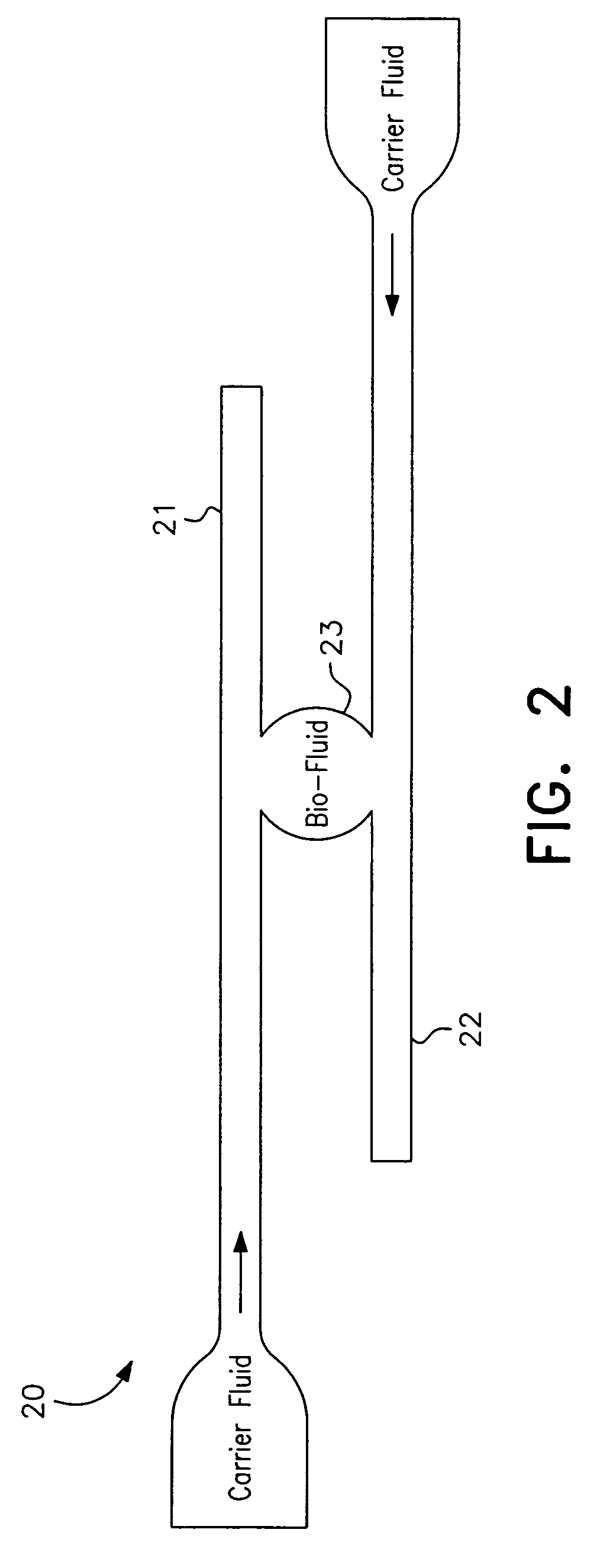
[0043]Referring to FIG. 2 a centrifuge device 20 of the sample preparation stage 6 is illustrated diagrammatically. It comprises opposed carrier...


PUM

PropertyMeasurementUnit
velocityaaaaaaaaaa
speedaaaaaaaaaa
velocitiesaaaaaaaaaa

Abstract

A microfluidic analysis system (1) performs polymerase chain reaction (PCR) analysis on a bio sample. In a centrifuge (6) the sample is separated into DNA and RNA constituents. The vortex is created by opposing flow of a silicon oil primary carrier fluid effecting circulation by viscous drag. The bio sample exits the centrifuge enveloped in the primary carrier fluid. This is pumped by a flow controller (7) to a thermal stage (9). The thermal stage (9) has a number of microfluidic devices (70) each having thermal zones (71, 72, 73) in which the bio sample is heated or cooled by heat conduction to / from a thermal carrier fluid and the primary carrier fluid. Thus, the carrier fluids envelope the sample, control its flowrate, and control its temperature without need for moving parts at the micro scale.

Description

[0001]This is a CONTINUATION of PCT / IE2004 / 000115 filed 6 Sep. 2004 and published in English, claiming the priorities of U.S. Application No. 60 / 500,344 and 60 / 500,345, both filed on 5 Sep. 2003.INTRODUCTION[0002]1. Field of the Invention[0003]The invention relates to analysis systems for analysis such as Polymerase Chain Reaction (PCR) analysis to detect the population of rare mutated cells in a sample of bodily fluid and / or tissue.[0004]2. Prior Art Discussion[0005]It is known for at least the past decade that cancers have a genetic cause. With the emergence of fast methods of sequencing and the publication of the human genome, the motivation and methods are available to find the genetic causes, both germline and somatic, of the most prevalent cancers. Contemporary oncological research suggests that there is a sequence of mutations that must occur for a cancer to be life-threatening, called the multistage model. Cancer could therefore be diagnosed earlier by detecting these geneti...

Claims


Application Information

Patent Timeline
Patent Type & Authority Patents(United States)
IPC IPC(8): G01N21/00B01F5/00B01F13/00B01L3/00B01L7/00
CPCB01F5/0057B01L3/50273B01L3/502776B01L7/525G01N35/08B01F13/0059G01N35/1095B01L2200/0636B01L2200/0673B01L2300/0816B01L2300/0861B01L2300/087B01L2300/185B01L2400/0409B01L2400/0487G01N2035/00514B01F25/10B01F33/30B01L3/502784B01L2200/141C12Q1/686
Inventor DAVIES, MARKDALTON, TARA
Owner STOKES BIO LTD
Why Eureka
Try Eureka