Interface for waveguide pin launch

a waveguide and interface technology, applied in the field of interfaces, can solve the problems of microwave energy being particularly difficult to control, energy waves are difficult to control on various circuits, and a portion of the signal is lost, so as to reduce the loss of signal

Active Publication Date: 2009-12-01
VIASAT INC
View PDF23 Cites 221 Cited by
  • Summary
  • Abstract
  • Description
  • Claims
  • Application Information

AI Technical Summary

Benefits of technology

[0008]In general, in accordance with one exemplary aspect of the present invention, an interface for connecting an integrated circuit such as a MMIC to a waveguide is provided. In one exemplary embodiment, the interface comprises a pin placed within an assembly which is configured to reduce signal loss. In another aspect of the present invention, two or more beads connect the pin to the assembly to further define the space. In yet another aspect of one exemplary embodiment, one bead is formed from glass to form a hermetic seal and the interface is connected to the integrated circuit.

Problems solved by technology

Energy waves can be difficult to control on various circuits, cables, wires, and other mediums that transport the energy waves because these mediums are “lossy.” Lossy materials and mediums loose energy by radiation, attenuation, or dissipation as heat.
By being lossy, a portion of the signal is lost as is travels through the circuits, wires, and other mediums.
Microwave energy is particularly difficult to control as many of the materials and mediums that transport microwave energy are lossy.
One exemplary circuit that generates and transports microwaves is a “monolithic microwave integrated circuit” or “MMIC.” Lost signal waves are unusable and decrease the efficiency of a MMIC as the signal strength decreases due to loss.
Generally, the higher the frequency of the microwave, the more lossy the transmission medium and more inefficient the circuit.
In certain applications, even signal losses that reduce the signal small amounts, such as 1 / 10 of a decibel, may result in a significant performance loss.
Unfortunately, signal loss is still problematic with certain waves because the connection or interface between the circuit generating the energy waves and the waveguide can be lossy itself.
This is especially an obstacle with a MMIC generating microwaves.
Moreover, impedance mismatches also cause signal losses.
However, current impendence matching interfaces between an integrated circuit such as a MMIC and a waveguide still have an unacceptable amount of loss.

Method used


Image

  • Interface for waveguide pin launch
  • Interface for waveguide pin launch
  • Interface for waveguide pin launch

Examples


Embodiment Construction

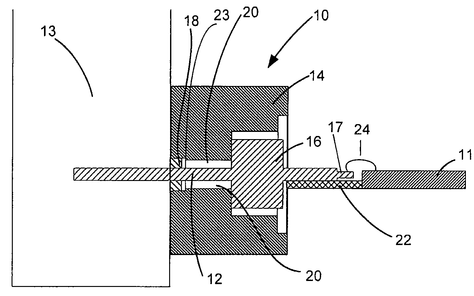
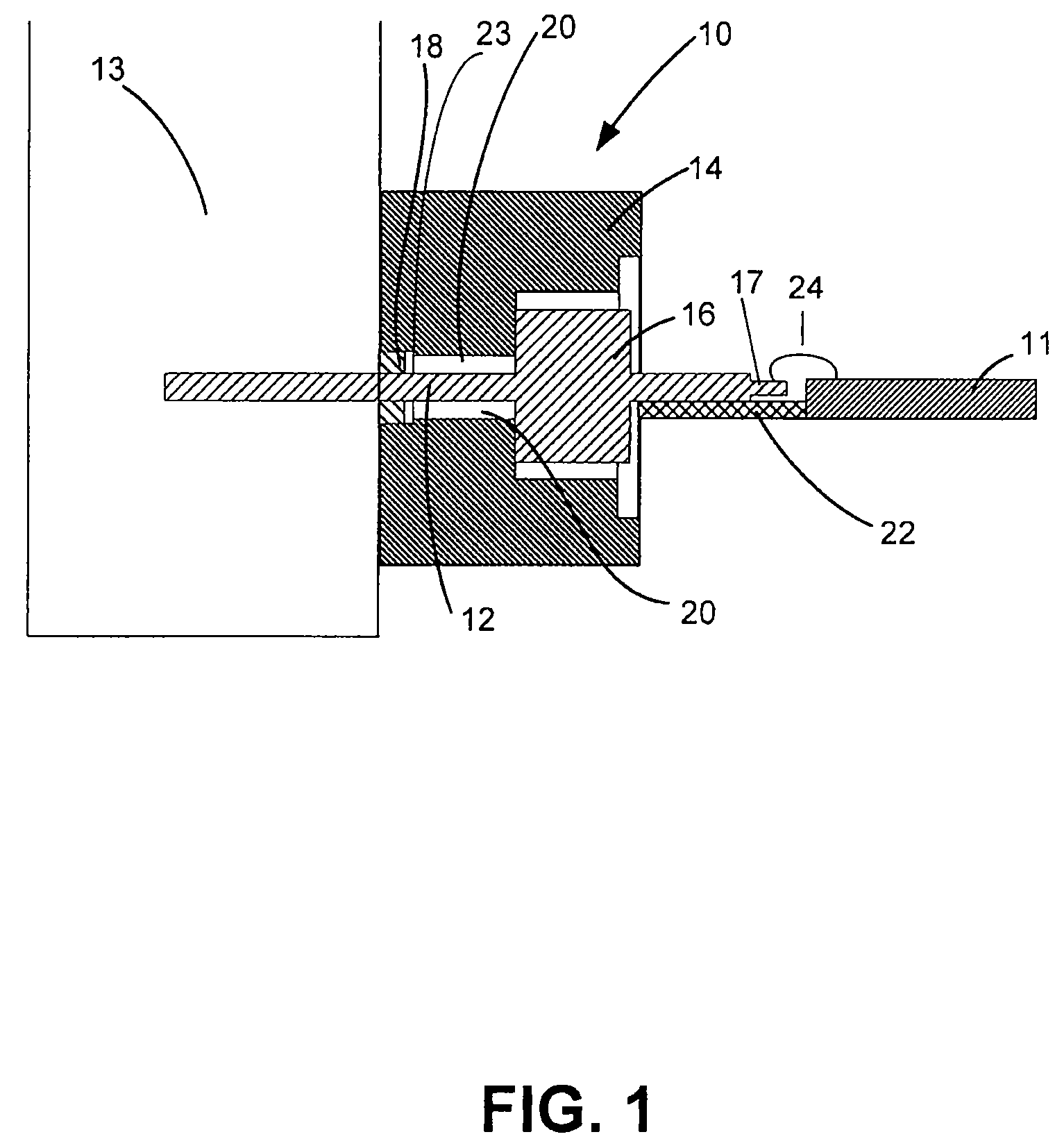
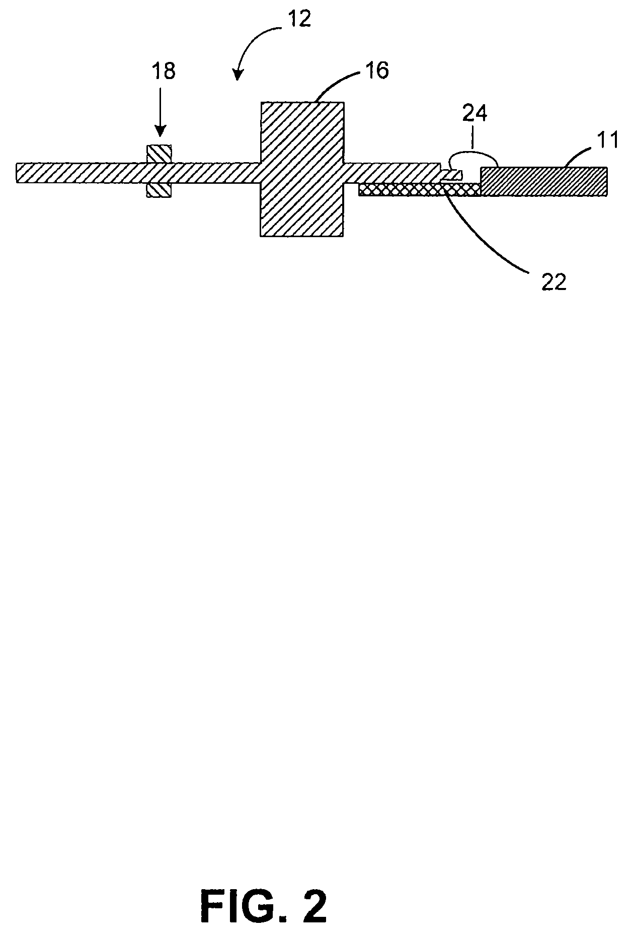
[0013]In accordance with one aspect of the present invention, an interface for connecting an integrated circuit to an energy transmission device such as a waveguide is disclosed. In accordance with another aspect of the present invention, a method of manufacturing an interface is disclosed. Throughout, the interface will be referred to as interface 10.

[0014]With reference to FIGS. 1-3, and in accordance with an exemplary embodiment of the present invention, interface 10 is a low-loss interface comprising a coaxial structure that is configured to transmit energy from one device to another. It should be noted that the term “low-loss” refers to the ability to reduce signal loss as discussed above. In an exemplary embodiment, interface 10 connects an integrated circuit 11 to another energy transmission device 13 and matches the impedance at integrated circuit 11 to the impedance at energy transmission device 13. Furthermore, interface 10 can be any device configured to transmit energy a...


PUM


Abstract

in general, in accordance with an exemplary aspect of the present invention, a low-loss interface for connecting an integrated circuit such as a monolithic microwave integrated circuit to an energy transmission device such as a waveguide is disclosed. In one exemplary embodiment, the interface comprises a pin seated within an assembly that forms a hermetic sealed, coaxial structure to prevent signal loss at increasing frequencies.

Description

FIELD OF INVENTION[0001]The present invention generally relates to an interface for use, for example, between an integrated circuit and a waveguide. More particularly, the present invention relates to an interface comprised of a low-loss pin and pin assembly that transports signals from, for example, an integrated circuit, such as a monolithic microwave integrated circuit, to a waveguide.BACKGROUND OF THE INVENTION[0002]There are numerous circuits and other electronic devices that produce energy waves such as electromagnetic waves and microwaves. These circuits produce energy waves that are delivered to a destination through different wires, guides, and other mediums.[0003]Energy waves can be difficult to control on various circuits, cables, wires, and other mediums that transport the energy waves because these mediums are “lossy.” Lossy materials and mediums loose energy by radiation, attenuation, or dissipation as heat. By being lossy, a portion of the signal is lost as is travels...

Claims


Application Information

Patent Timeline
Patent Type & Authority Patents(United States)
IPC IPC(8): G02B6/36
CPCH01P5/085
Inventor ZIENKEWICZ, ROBHARPER, DAVEBUER, KENNETH VDECAMP, JOHN
Owner VIASAT INC
Why Eureka
Try Eureka