
Retractable optical fiber tether assembly and associated fiber optic cable

a technology of optical fiber tether and associated fiber optic cables, which is applied in the direction of optical light guides, fibre mechanical structures, instruments, etc., can solve the problems of difficult scaling, complicated distribution and use, and relatively complex wireless system/network,

Inactive Publication Date: 2009-12-01
CORNING OPTICAL COMM LLC
View PDF1 Cites 56 Cited by
  • Summary
  • Abstract
  • Description
  • Claims
  • Application Information

AI Technical Summary

Problems solved by technology

This makes the wireless system / network relatively complex and difficult to scale, particularly when many picocells need to cover a large region.
Further, the digital information processing performed at the access point devices requires that these devices be activated and controlled by the head-end controller, which further complicates the distribution and use of numerous access point devices to produce a large picocellular coverage area.
While radio-over-fiber (RoF) wireless picocellular systems are generally robust, there are some limitations.
One limitation relates to the radiation pattern from the transceiver antenna.
Though microstrip antennas have a directional radiation pattern, they are generally more expensive and more complicated to integrate into a RoF cable than the simpler and less expensive dipole antennas.
This wastes energy and also interferes with other picocells, such as those formed in the floor above the ceiling in which the RoF cable is deployed.
Another limitation relates to the need for having a transceiver for each picocell.
A further limitation relates to locating RoF transceivers after they are deployed.
This makes it difficult for service personnel to locate a problematic transceiver.

Method used


Image

  • Retractable optical fiber tether assembly and associated fiber optic cable
  • Retractable optical fiber tether assembly and associated fiber optic cable
  • Retractable optical fiber tether assembly and associated fiber optic cable

Examples


Embodiment Construction

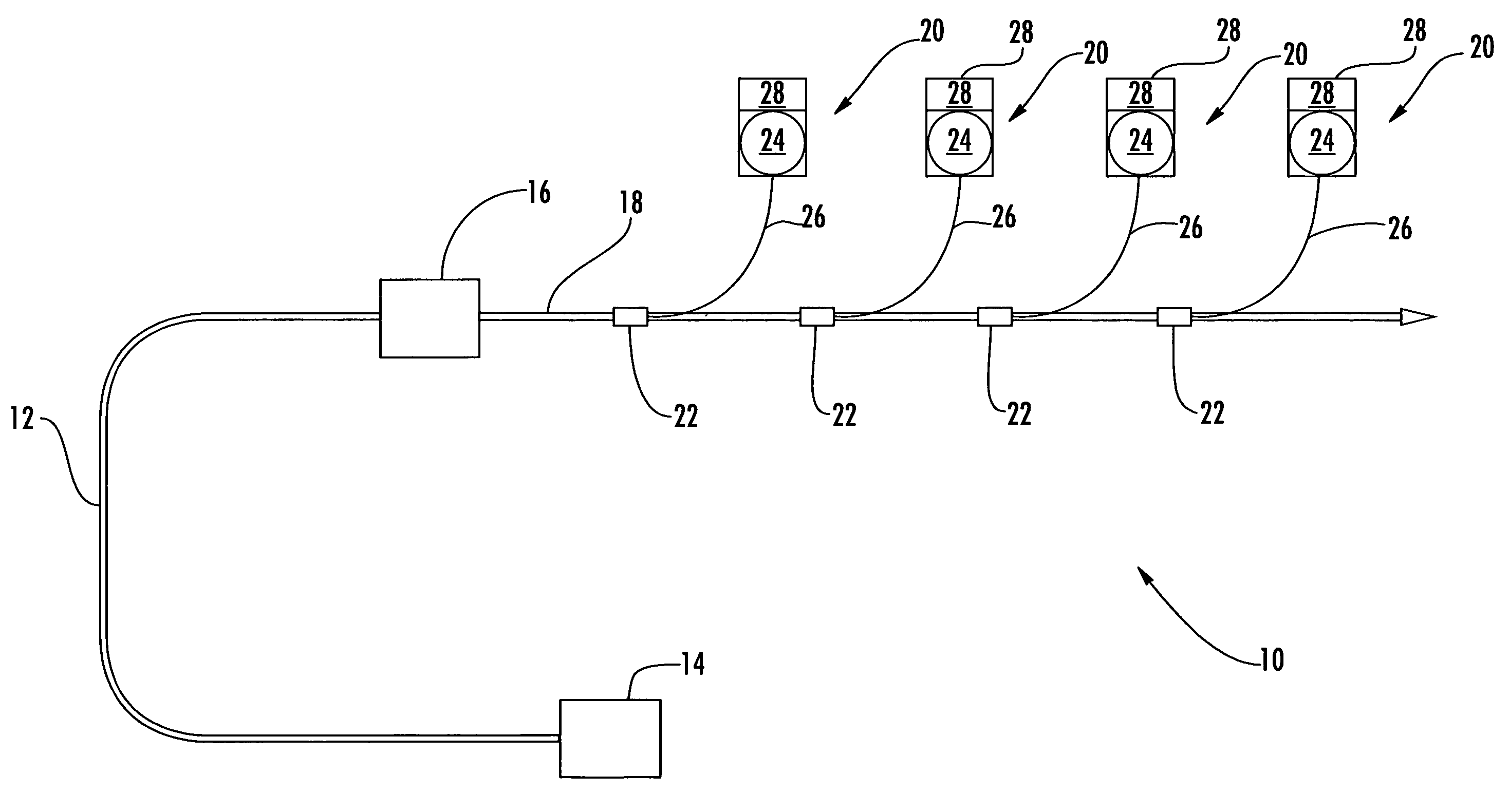
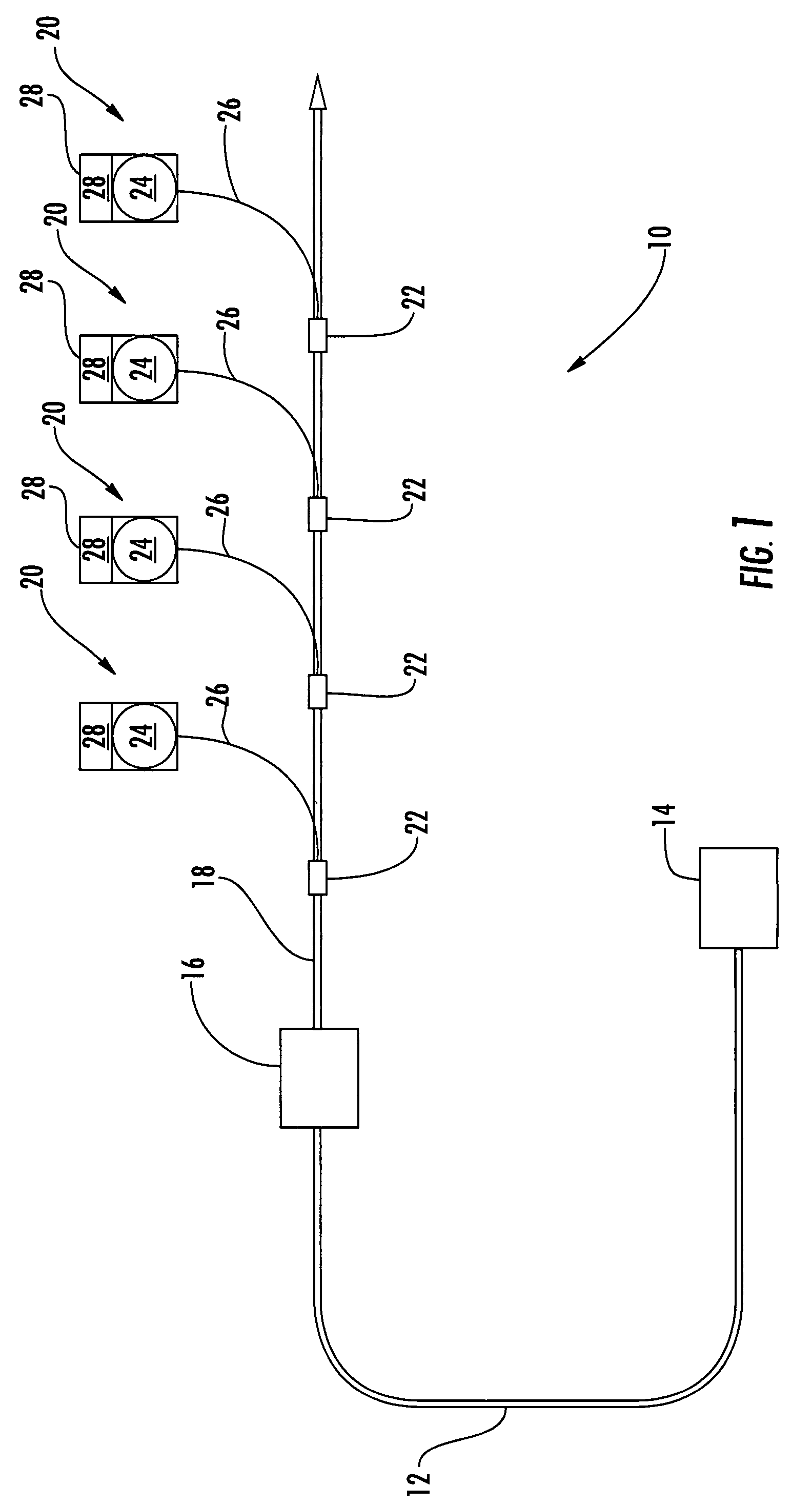
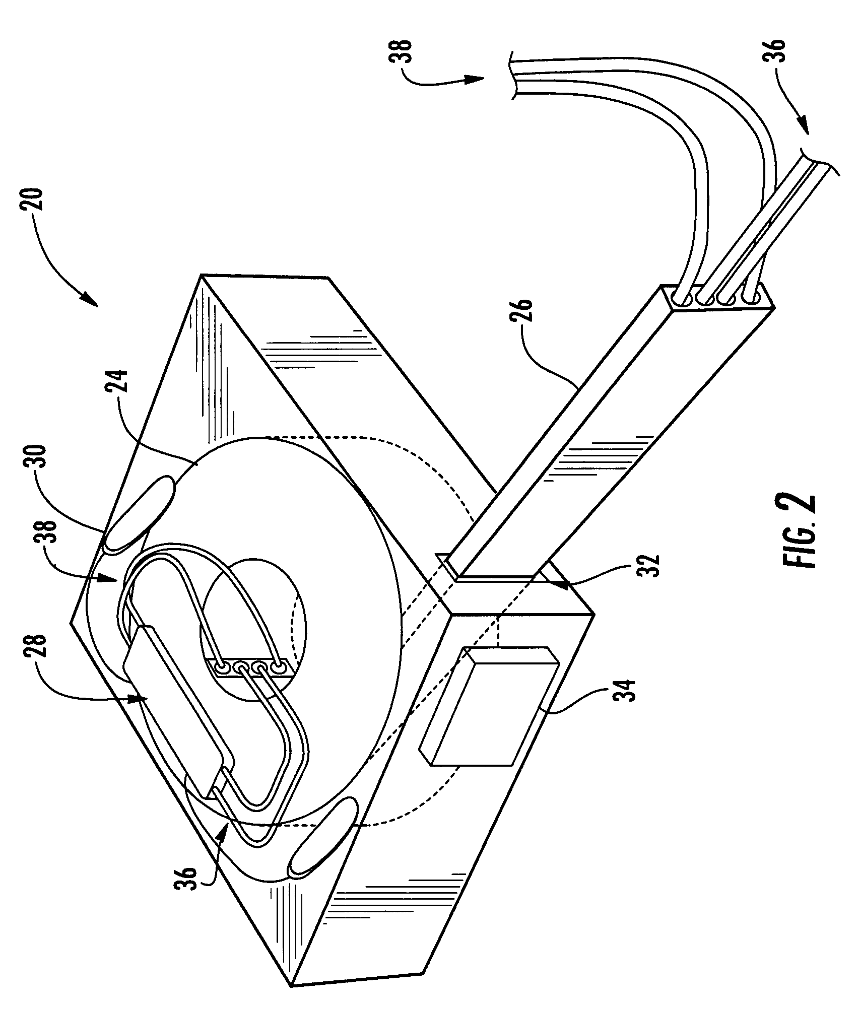
[0029]In various exemplary embodiments, the present invention provides an optical system that allows for the flexible location of an optical device that is coupled to a patch panel in a wiring closet or other optical signal source through a series of fiber optic cables and optical connections, or the flexible location of an array of such optical devices. The optical system includes, in part, one or more retractable optical fiber tether assemblies that each allow varying lengths of tether cable to be pulled and used. The retraction device of each of the optical tether assemblies may be disposed mid-tether cable, or may terminate the respective tether cable and incorporate the given optical device. In the exemplary WLAN application, each of the retractable optical fiber tether assemblies includes an integral transceiver and associated software. Thus, each of the retractable optical fiber tether assemblies functions as an antenna. The associated fiber optic cable carries both optical f...


PUM


Abstract

The present invention provides an optical system that allows for the flexible location of an optical device that is coupled to a patch panel in a wiring closet or other optical signal source through a series of fiber optic cables and optical connections, or the flexible location of an array of such optical devices. The optical system includes, in part, one or more retractable optical fiber tether assemblies that each allow varying lengths of tether cable to be pulled and used. The retraction device of each of the optical tether assemblies may be disposed mid-tether cable, or may terminate the respective tether cable and incorporate the given optical device. In an exemplary wireless local area network (WLAN) application, each of the retractable optical fiber tether assemblies includes an integral transceiver and associated software. Thus, each of the retractable optical fiber tether assemblies functions as an antenna. The associated fiber optic cable carries both optical fiber to provide optical continuity and copper wire to provide electrical conductivity to the antenna array.

Description

BACKGROUND OF THE INVENTION[0001]1. Field of the Invention[0002]The present invention relates generally to an assembly that allows for the flexible location of an optical device within an optical communications network, and more specifically to a retractable optical fiber tether assembly and the associated fiber optic cable. In one exemplary application, a plurality of these retractable optical fiber tether assemblies are used to flexibly deploy an antenna array for a wireless local area network (WLAN) or the like, the associated fiber optic cable carrying both optical fiber to provide optical continuity and copper wire to provide electrical conductivity to the antenna array.[0003]2. Technical Background of the Invention[0004]In various applications, it is desirable to flexibly locate an optical device that is coupled to a patch panel in a wiring closet or other optical signal source through a series of fiber optic cables and optical connections, or to flexibly locate an array of su...

Claims


Application Information

Patent Timeline
Patent Type & Authority Patents(United States)
IPC IPC(8): G02B6/00G02B6/44
CPCG02B6/4457G02B6/4403G02B6/4416
Inventor HURLEY, WILLIAM CARL
Owner CORNING OPTICAL COMM LLC
Learn More