Multifunctional collimator indicator

a collimator indicator and multi-functional technology, applied in the direction of static indicating devices, navigation instruments, instruments, etc., can solve the problems of difficulty in obtaining quality and timely readings, difficult conditions for obtaining quality readings, severe handicaps one's judgment, etc., and achieve the effect of facilitating chang

Inactive Publication Date: 2009-12-08
LVOVSKIY MATVEY +3
View PDF18 Cites 23 Cited by
  • Summary
  • Abstract
  • Description
  • Claims
  • Application Information

AI Technical Summary

Benefits of technology

[0031]Immediate angular field of view of the upper channel provides the ability to view the graphical display of all necessary parameters of a moving vehicle on an exterior environment of the windshield and with no head movements required by the driver. The immediate angular field of view of the lower channel is equivalent to the angular size of a standard traditional vehicular dashboard.
[0032]The disclosed collimator indicator is equipped with a CPU, the inlets of which are connected with corresponding sensors such as speed sensors, engine rotation sensors, oil sensors, navigation system e.t.c. The outlets of the indicator are connected with the inlets of the image formulator. The drawing of the desired virtual designs for gauges and background is accomplished with the use of computer programming at the time of production and can be easily changed at any time by reprogramming of the computer system.

Problems solved by technology

While engaged in the activity of obtaining updated reading off the navigational display, the driver's ability to track the ever changing conditions of the outside environment is limited only to peripheral vision which severely handicaps one's judgment, especially in extreme conditions.
One of the most challenging conditions for obtaining quality readings pertains to convertible automobiles.
In these autos, the quality of the reading acquisition process from vehicular gauges and navigational displays is directly subjected to the intensity of direct sunlight, causing hardship in obtaining quality and timely readings.
The usage of sunshields on the gauges helps however does not serve as a solution to the problem.
The glance shifting of the eyes between the outside environment, vehicular gauges, and the satellite navigational map requires constant accommodations and readjustments of the eyes which subsequently dictates a certain delay.
The significant valid differentiation factors in lighting conditions inside and outside of the vehicle causes further significant time delay in visual eye adjustments.
The above stated factors subsequently influence the driver's overall state, judgment and reactions, by so causing decline in safety of the vehicle's operability, especially under severe conditions.
Thus, the combined presences of the 3 above stated independent visual sources of information, located in different places inside a vehicle varying in operation, functionality, design and that are intended to facilitate safe operability of a motor vehicle, in actuality worsen a number overall safety factors.
For instance, the windshield projection of gauges and / or navigational map is not practical as the overabundance of images displayed onto the windshield can interfere with driver's awareness of the external environment which subsequently can contribute to a hazardous condition.The usage of a semitransparent mirror providing the ability for visual tracking of data projected onto the windshield simultaneously with the identical image formulated on the dashboard significantly diminishes the brightness of both displays in turn negatively affecting the contrast of both displays, especially in highly illuminated external environments such as direct sunlight, tunnels and garages.
The suggested system is once again unreasonably overcomplicated and possesses low sensitivity due to significant light loss while passing through the optical system of the device.

Method used


Image

  • Multifunctional collimator indicator
  • Multifunctional collimator indicator
  • Multifunctional collimator indicator

Examples


Embodiment Construction

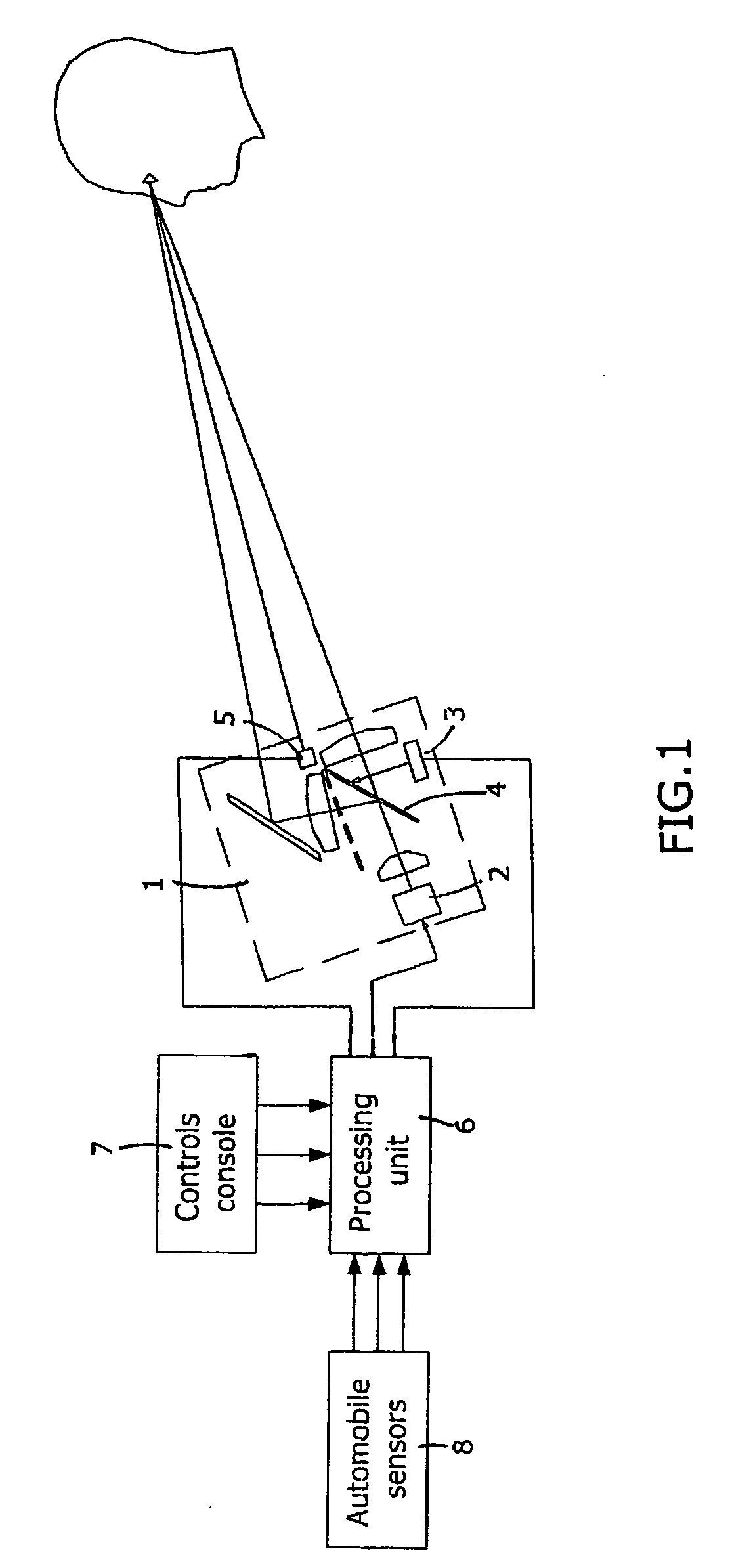
[0038]FIG. 1 shows a structural diagram of the vehicular multifunctional collimator indicator. It consists of the indication unit 1, which contains the image formulator 2, additional elements of the optical system, servo 3, rotating mirror 4, and the viewing direction sensor 5, the last being an integral part of the system responsible for determining the direction of the driver's view. The indicator also consists of a processing unit 6, and the controls console 7 that can be positioned nearby the indication unit or elsewhere as independently constructed modules. Some inlets of the processing unit 6 are connected with the automobile sensors 8, and other inlets of the processing unit 6 are connected with the controls console 7 and the viewing direction sensor 5. The outlets of the processing unit 6, are connected with the image formulator 2 and servo 3.

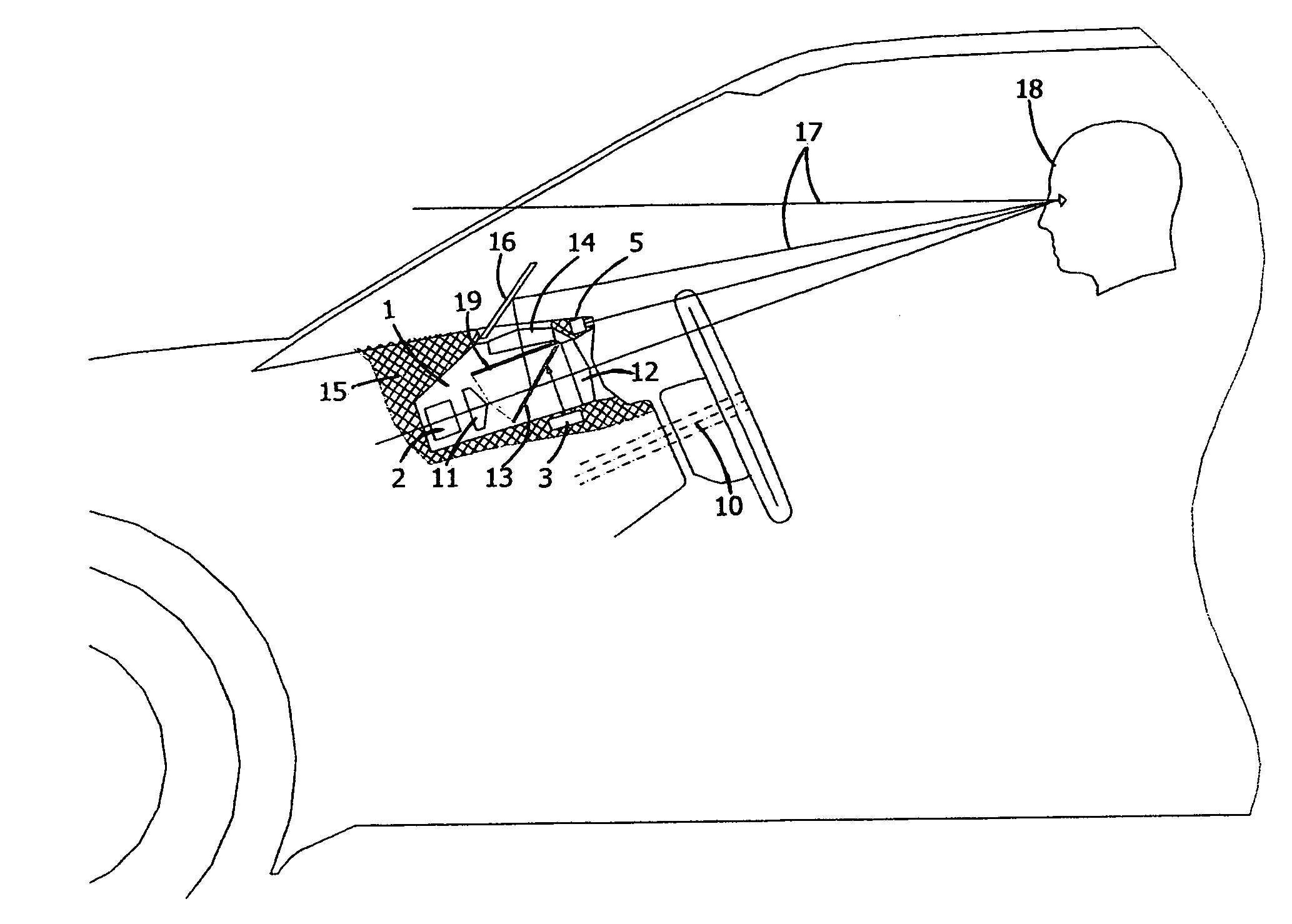
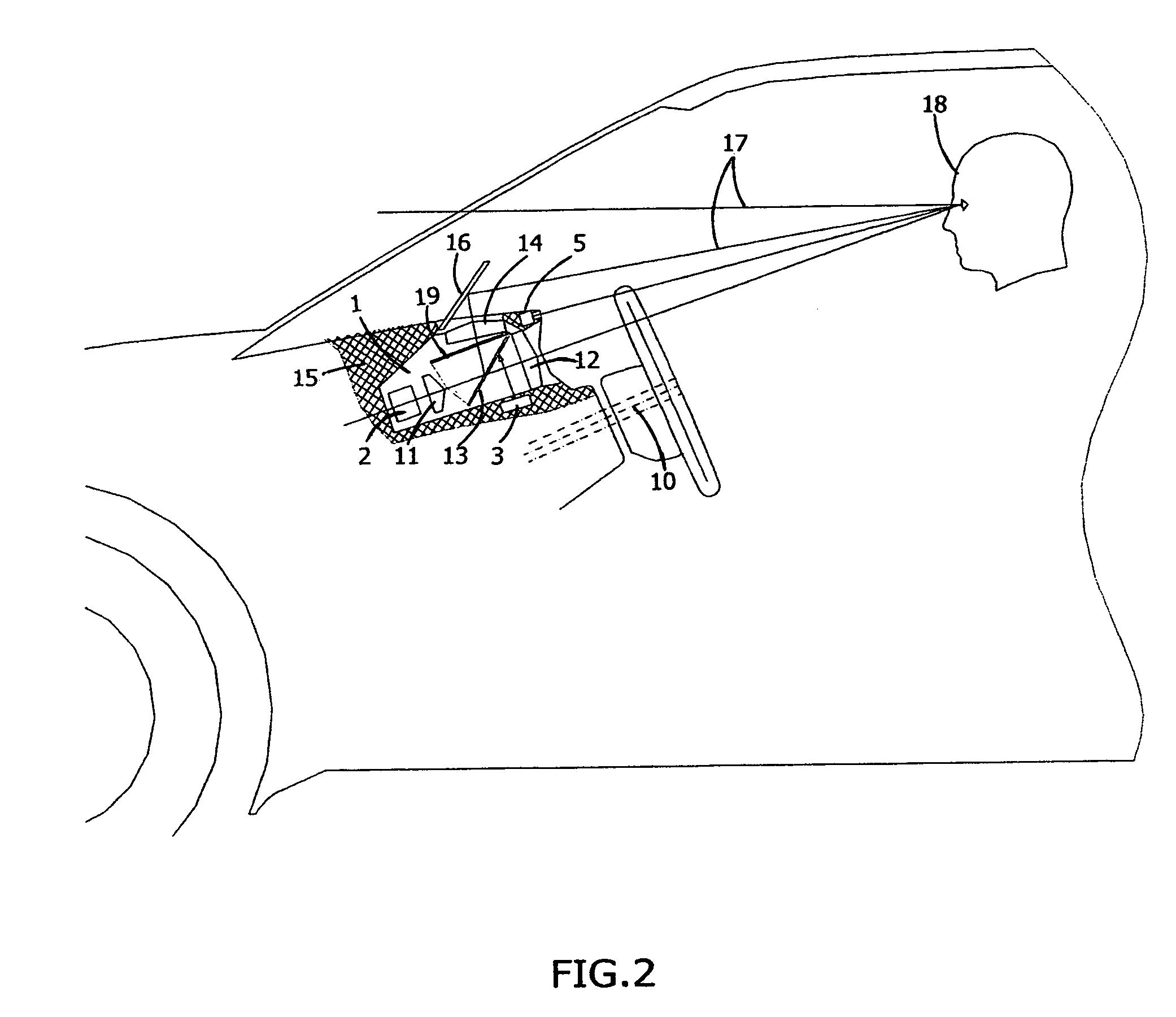
[0039]FIG. 2 shows a constructive diagram of the indication unit 1, which is placed inside of a vehicle 9 in place of the traditional ...


PUM


Abstract

The present invention relates to indication systems providing augmented visual support for the operator of a motor vehicle, vessel or an aircraft. The indication system is positioned in the location of a traditional vehicular gauge dashboard. The indication system consists of an image formulator and an optical collimator system with two visual channels. Lower channel is used for direct visual tracking of all virtual gauge readings while the upper channel is used to track updates “on the windshield” of a vehicle with the background of the surrounding environment. The lower channel displays virtual collimator imaging of the traditional analog or digital gauges as well as navigational system data. The upper channel is reflected onto the exterior background of the windshield and displays collimator imaged critical data that is required for the safe operation of a vehicle. To provide the switching functionality between the two channels, the indication system utilizes a lightproof partition. The side of the partition facing the image formulator is designed as a flat reflective mirror. In order to engage the lower channel, the partition is placed away from the optical systems for the lower channel. To provide viewing of the upper channel, the partition is positioned along the optical axis of the upper collimator lens at a given angle. To provide the function of automatic switching between the channels, the multifunctional collimator indicator is equipped with an eye position tracking system which tracks real-time position of the eye's pupil.

Description

BACKGROUND OF THE INVENTION[0001]The present invention relates to devices providing visual indication of elapsed and ongoing values and parameters of a moving object such as speed, distance traveled, engine rotation, oil pressure, fuel reading, satellite navigational map readings as well as various warnings. The device is intended for usage on various types of automobiles and other vehicles including military transports used on the ground, air or water and require human interaction. The principal difference of the present invention is as follows:[0002]Vehicular data as mentioned above and that is formulated within driver's line of sight is displayed via collimated means.[0003]The shape, size and the color spectrum of the presented data is derived from the 2 primary direction positions of the driver's view: the dashboard or the outside environment.[0004]Display mode adjustments are fully automatic and are derived from the direction of the driver's view by tracking positioning of the ...

Claims


Application Information

Patent Timeline
Patent Type & Authority Patents(United States)
IPC IPC(8): B60Q1/00
CPCG02B27/01G02B27/0101G02B2027/0118B60K2350/2052G02B2027/0165G02B2027/0187G02B2027/0138B60K2370/334
Inventor LVOVSKIY, MATVEYIOKHVIDSON, SIMONLVOVSKY, MIKHAILEFROS, ALEXANDER
Owner LVOVSKIY MATVEY
Why Eureka
Try Eureka