Secondary battery charge/discharge electricity amount estimation method and device, secondary battery polarization voltage estimation method and device and secondary battery remaining capacity estimation method and device

a technology of secondary battery and electricity amount, which is applied in the direction of battery/fuel cell control arrangement, instruments, electrochemical generators, etc., can solve the problems of increasing the cost, no other way than to use an inexpensive current sensor having a relatively low precision, and the estimation method is not easy to achieve. , to achieve the effect of prolonging the life of the battery and improving the accuracy of the soc estimation

Active Publication Date: 2009-12-08
PANASONIC EV ENERGY CO LTD
View PDF5 Cites 16 Cited by
  • Summary
  • Abstract
  • Description
  • Claims
  • Application Information

AI Technical Summary

Benefits of technology

[0036]According to the present invention, an estimated charging/discharging electricity amount including substantially no current measurement error is calculated based on a measured voltage involving little influence from current measurement error (a zero-current state voltage calculated from a no-load voltage or an open-circuit vol...

Problems solved by technology

However, the above conventional SOC estimation method has the following problems.
When a high-precision current sensor is used, the cost will increase.
Thus, there is no other way but to use an inexpensive current sensor having a relatively low precision.
A current value detected with such a current sensor includes a measurement error.
In particular, when the charging/discharging rate is smaller than the current error (when, for example, the charging/discharging rate is 1 A and the current error is ±2 A), the estimated SOC starts to behave in an unpredictable manner as time elap...

Method used


Image

  • Secondary battery charge/discharge electricity amount estimation method and device, secondary battery polarization voltage estimation method and device and secondary battery remaining capacity estimation method and device
  • Secondary battery charge/discharge electricity amount estimation method and device, secondary battery polarization voltage estimation method and device and secondary battery remaining capacity estimation method and device
  • Secondary battery charge/discharge electricity amount estimation method and device, secondary battery polarization voltage estimation method and device and secondary battery remaining capacity estimation method and device

Examples


first embodiment

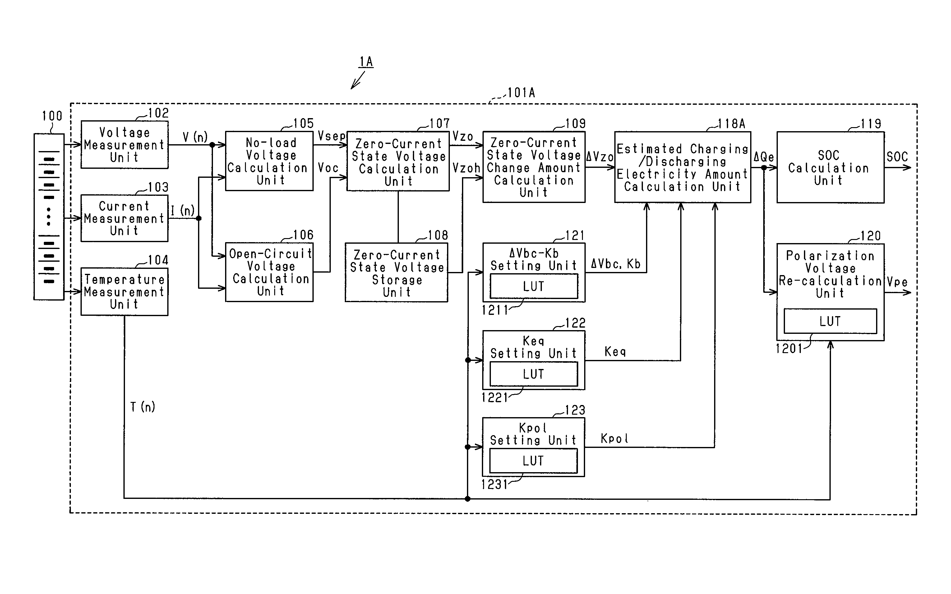
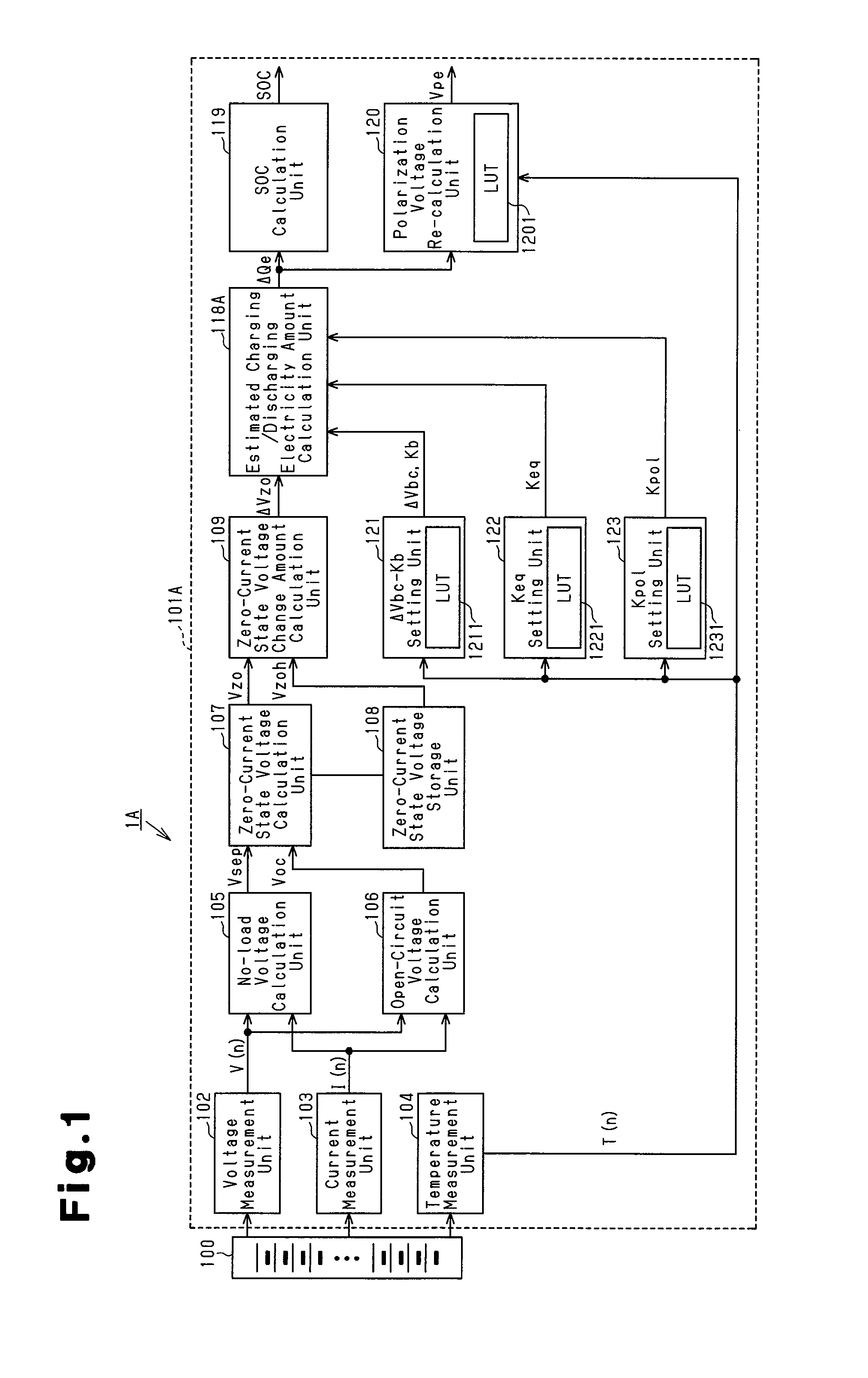
[0082]FIG. 1 is a block diagram showing an example structure for a battery pack system according to a first embodiment of the present invention. In FIG. 1, a battery pack system 1A includes a battery pack 100 and a battery ECU 101A including an SOC estimation apparatus of the present invention which is part of a microcomputer system.

[0083]The battery pack 100, mounted for example on an HEV, is formed by a plurality of battery blocks that are electrically connected in series. Each battery block is formed by a plurality of cells or battery modules, e.g., nickel-metal hydride batteries, which are electrically connected in series in order to obtain a predetermined output to a motor.

[0084]The battery ECU 101A includes a voltage measurement unit 102 for measuring a terminal voltage for each battery block in the battery pack 100 detected by a voltage sensor (not shown) in predetermined sampling cycles as voltage data V(n), a current measurement unit 103 for measuring a charging / discharging...

second embodiment

[0109]FIG. 3 is a block diagram showing an example structure of a battery pack system 1B according to a second embodiment of the present invention. In FIG. 3, the components having the same structure and functions as the components of the first embodiment illustrated in FIG. 1 will be given the same reference numbers as those components and will not be described.

[0110]A battery ECU 1B of the present embodiment calculates an estimated charging / discharging electricity amount ΔQe not only by using a zero-current state voltage change amount ΔVzo as in the first embodiment but also by obtaining a time-dependent voltage change amount ΔVbp(th) from a stored polarization voltage Vph and a storage time th and using the time-dependent voltage change amount ΔVbp(th) instead of using a voltage change amount adjustment coefficient ΔVbc.

[0111]In FIG. 3, an estimated charging / discharging electricity amount ΔQe from an estimated charging / discharging electricity amount calculation unit 118B is input...

third embodiment

[0120]FIG. 6 is a block diagram showing an example structure of a battery pack system 1C according to a third embodiment of the present invention. In FIG. 6, the components having the same structure and functions as the components of the first and second embodiments illustrated in FIGS. 1 and 3 will be given the same reference numbers as those components and will not be described.

[0121]A battery ECU 1C of the present embodiment calculates an estimated charging / discharging electricity amount ΔQe not only by using a zero-current state voltage change amount ΔVzo as in the first embodiment but also by calculating an electromotive force Veq1 from a zero-current state voltage Vzo and a polarization voltage Vpol, obtaining an electromotive force change amount ΔVeq from a stored electromotive force Veq1, and using a value obtained by dividing an electromotive force change coefficient ΔVeq by a measured charging / discharging electricity amount ΔQm obtained from current data I(n) instead of us...


PUM


Abstract

If a particular selection condition is satisfied, a non-load voltage calculation unit (105) calculates a no-load voltage Vsep as a voltage piece when the current in approximate straight line obtained by statistical processing using the method of least squares for a plurality of sets of data containing current data I(n) and voltage data V(n) is zero. If a particular current condition or voltage condition is continuously satisfied for a predetermined time, an open-circuit voltage calculation unit (106) calculates a secondary cell terminal voltage as an open-circuit voltage Voc and a voltage-at-zero-current storing unit (108) stores voltage-at-zero-current Vzo calculated by a voltage-at-zero-current calculation unit (107). By using a predetermined voltage change amount adjustment constant ΔVbc/adjustment coefficient Kb, an electromotive force change constant Keq, and a polarization voltage generation constant Kpol, an estimated charge/discharge electric amount calculation unit (118A) calculates an estimated charge/discharge electricity amount ΔQe as a function of the change amount ΔVzo of a voltage-at-zero-current Vzo. It is possible to estimate charge/discharge electricity amount without being affected by the current measurement error.

Description

FIELD OF THE INVENTION[0001]The present invention relates to a technique for estimating the state of charge (SOC) of a rechargeable battery such as a nickel-metal hydride battery (Ni-MH) mounted on a pure electric vehicle (PEV), a hybrid electric vehicle (HEV), and the like as a power source for a motor or a drive source for various loads.BACKGROUND OF THE INVENTION[0002]An HEV conventionally executes state of charge (SOC) control on a rechargeable battery to maximize fuel consumption efficiency of the vehicle by detecting voltage, current, temperature, and the like of the rechargeable battery and performing calculations to estimate the SOC of the rechargeable battery. For accurate execution of the SOC control, the SOC of the rechargeable battery during charging / discharging needs to be estimated correctly.[0003]In one conventional method for estimating the SOC, a battery voltage V and a charge-discharge current I are measured over a predetermined period, an integrated value ∫I of th...

Claims


Application Information

Patent Timeline
IPC IPC(8): G06F19/00G01R31/36H01M10/48
CPCG01R31/3651G01R31/3624G01R31/3842G01R31/367Y02E60/10H01M10/48G01R31/3648G01R31/52G01R19/12B60L58/12
Inventor MURAKAMI, YUSAI
Owner PANASONIC EV ENERGY CO LTD
Why Eureka
Try Eureka