Mass-flow sensor with a molded flow restrictor

Inactive Publication Date: 2009-12-15
HONEYWELL INT INC
View PDF20 Cites 35 Cited by
  • Summary
  • Abstract
  • Description
  • Claims
  • Application Information

AI Technical Summary

Benefits of technology

[0009]The aforementioned aspects and other objectives and advantages can now be achieved as described herein. A mass-flow sensing device and a method of forming the same are disclosed. The mass-flow sensing device/apparatus generally includes a flow tube bypassed in a flow path defined by a flow channel, through which a fluid flows. The flow tube is preferably formed from a plastic material, but may be formed from another material. A flow sensor (e.g., an airflow sensor) can be disposed in the plastic flow tube for measuring a flow rate of the fluid in the flow channel. A set of narrow rectangular flow restrictors can be molded into the plastic flow tube and positioned adjacent to the airflow sensor. The rectangular flow restrictors have a laminarizing effect on the flow of the fluid in the flow tube,

Problems solved by technology

Such flow sensors are susceptible to mis-measurement due to turbulent flow effects (e.g., non-uniformity in flow velocity and pressure), and thus the accuracy of such sensors may b

Method used


Image

  • Mass-flow sensor with a molded flow restrictor
  • Mass-flow sensor with a molded flow restrictor
  • Mass-flow sensor with a molded flow restrictor

Examples


Embodiment Construction

[0016]The particular values and configurations discussed in these non-limiting examples can be varied and are cited merely to illustrate at least one embodiment and are not intended to limit the scope thereof.

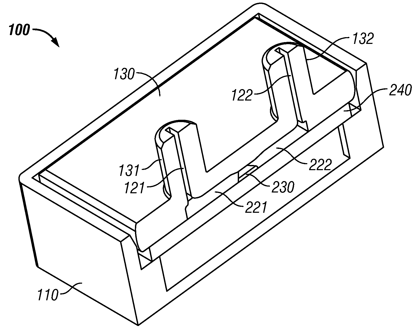
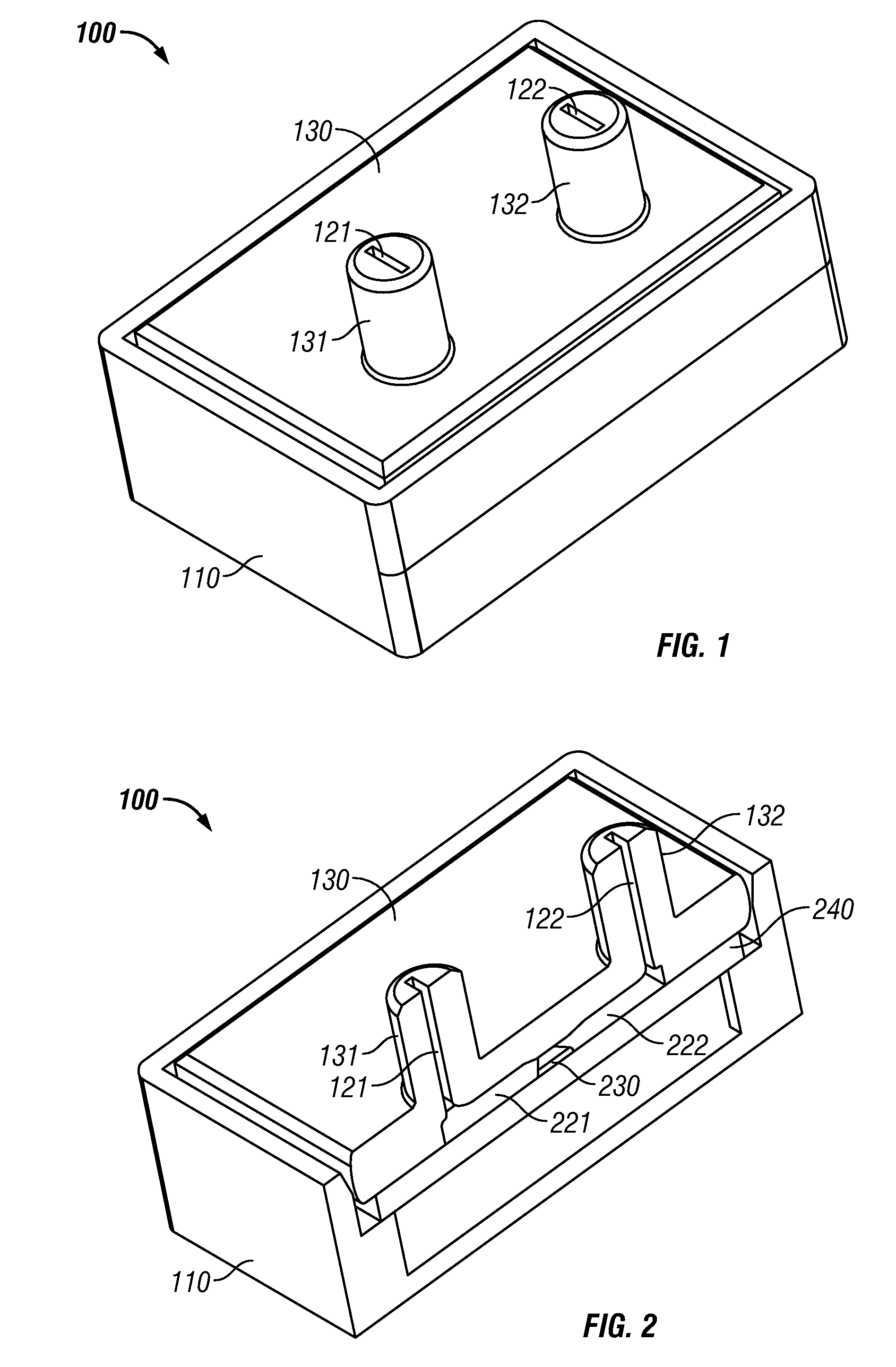
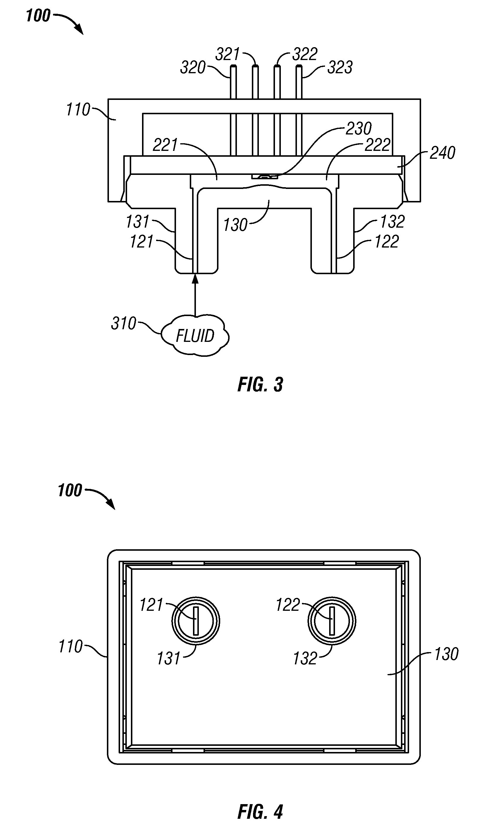
[0017]FIG. 1 illustrates a general perspective view of a mass-flow sensing apparatus 100, which can be adapted for use in implementing a preferred embodiment. The mass-flow sensing apparatus 100 can include a body 110 and flow tube 130 which can be fitted with ports 131 and 132 having restrictors 121 and 122, so that a fluid enters restrictor 121, flows through flow channel 221 and 222 as depicted in FIG. 2 and exits the restrictor 122. Note that as utilized herein the term “fluid” can refer to a gas and / or a liquid. Thus, the high mass-flow sensing apparatus 100 can be utilized in a flow system (not shown) for measuring a flow rate of the fluid. Note that the embodiments discussed herein generally relate to an airflow sensing system. It can be appreciated, however, that such e...


PUM


Abstract

A high mass-flow sensing apparatus and method of forming the same, comprising a flow tube bypassed in a flow path defined by a flow channel, through which a fluid flows. A flow sensor can be disposed in the flow tube for measuring a flow rate of the fluid in the flow channel. A set of narrow rectangular flow restrictors can be molded into the flow tube and adjacent to the flow sensor. Each flow restrictor can include several rectangular cutouts that are molded into upstream and/or downstream portions of the flow tube in order to limit the flow rate of the fluid across the flow sensor. The flow restrictors can laminarize the flow rate of the fluid in the flow tube and thereby reduce flow turbulence and lead to optimal sensing performance of the flow sensor.

Description

TECHNICAL FIELD[0001]Embodiments are generally related to mass-flow sensing devices and methods. Embodiments are also related to airflow sensors that incorporate the use of a molded flow restrictor. Embodiments are additionally related to an improved method for providing flow restriction utilizing a flow restrictor.BACKGROUND OF THE INVENTION[0002]Fluid flow rate control mechanisms are utilized in a variety of flow systems in order to control the amount of fluid such as, for example, gas or liquid, passing through a flow system. Flow control mechanisms can be utilized to regulate flow rates in systems such as ventilators and respirators for maintaining a sufficient flow of breathable air or providing sufficient anesthetizing gas to a patient in preparation for surgery. Typically, flow rate control occurs through the utilization of control circuitry responsive to measurements obtained from fluid flow sensors. Such a fluid flow sensor may be configured to measure properties of a fluid...

Claims


Application Information

Patent Timeline
IPC IPC(8): G01F1/37
CPCG01F1/68G01F15/185G01F15/14G01F15/00
Inventor SPELDRICH, JAMIE
Owner HONEYWELL INT INC
Why Eureka
Try Eureka