
Haze-resistant low-emissivity coatings

a technology of low emissivity and film stack, applied in the field of transparent film stack, can solve the problems of haze development within the film stack, inability to withstand such temperatures, and expensive coatings,

Inactive Publication Date: 2009-12-15
CARDINAL CG
View PDF62 Cites 24 Cited by
  • Summary
  • Abstract
  • Description
  • Claims
  • Application Information

AI Technical Summary

Benefits of technology

The invention provides a sheet-like substrate with a low-emissivity coating that includes an inner dielectric layer, two infrared-reflective layers, a middle coat comprising two zinc tin oxide film regions, a second infrared-reflective layer, and an outer dielectric layer. The coating has a thickness of less than 100 angstroms and is effective in blocking infrared radiation. The method of producing the coated glass article involves depositing the various layers in a specific order and using specific materials. The technical effects of the invention include improved insulation, reduced heat transfer, and improved energy efficiency in the production of coated glass articles.

Problems solved by technology

Film stacks employing silver as an infrared-reflective film often cannot withstand such temperatures without some deterioration of the silver film.
Particularly for bent glass articles, though, this procedure may produce non-uniform coatings and is costly.
One further problem encountered during tempering is the development of a haze within the film stack.
This, it is surmised, causes haze in the coating when it is treated at elevated temperatures.
If the 5-layer Oyama et al. film stack were tempered at elevated temperatures, it is rather likely that the silver layers would be oxidized sufficiently to render the resulting coated glass article unsellable.

Method used


Image

  • Haze-resistant low-emissivity coatings
  • Haze-resistant low-emissivity coatings
  • Haze-resistant low-emissivity coatings

Examples


Embodiment Construction

[0018]The following detailed description is to be read with reference to the drawings, in which like elements in different drawings have been given like reference numerals. The drawings, which are not necessarily to scale, depict selected embodiments and are not intended to limit the scope of the invention. Skilled artisans will recognize that the examples given have many useful alternatives that fall within the scope of the invention.

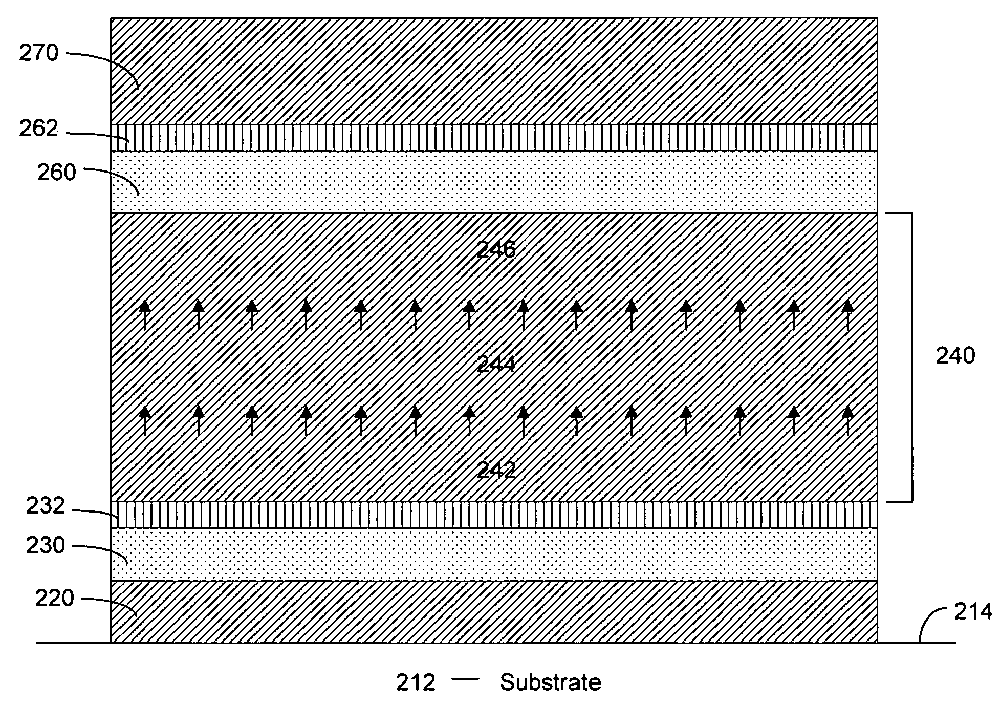
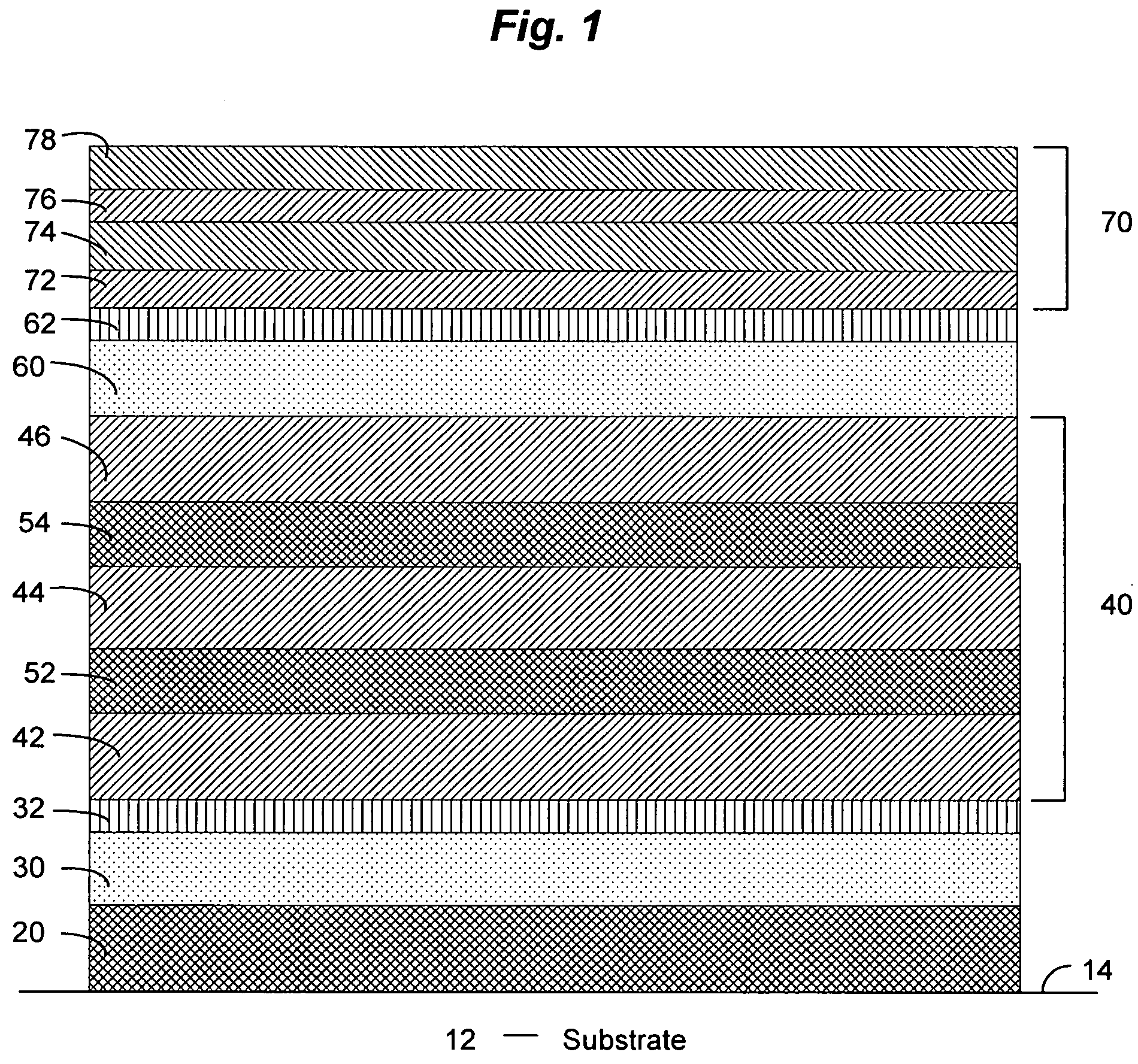
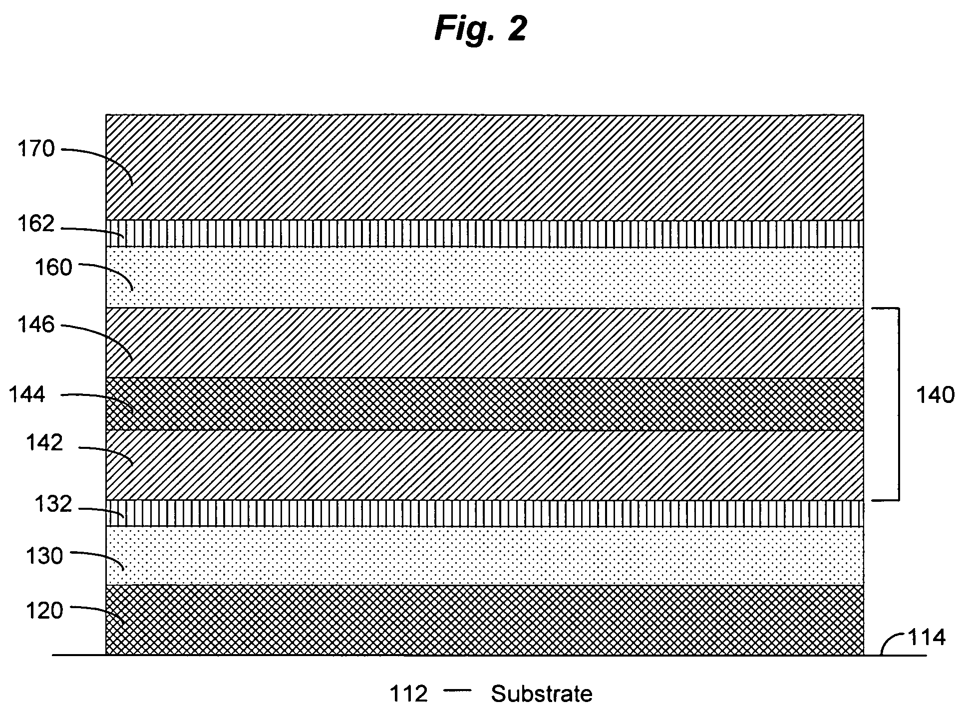
[0019]FIG. 1 schematically illustrates a substrate 12 bearing a coating in accordance with one embodiment of the invention. It should be understood that this drawing is intended merely to illustrate concepts of the invention and the thicknesses of the various layers in the drawing are not to scale. The substrate 12 in this drawing comprises a coating of the invention applied to a surface 14. While opaque substrates may be used, it is anticipated that for most applications of this invention, the substrate 12 will comprise a transparent or translucent ma...


PUM

PropertyMeasurementUnit
thicknessaaaaaaaaaa
thicknessaaaaaaaaaa
thicknessaaaaaaaaaa

Abstract

A substrate bearing a low-emissivity coating, the coating comprising two infrared-reflective layers separated by a middle coat, the middle coat comprising two zinc tin oxide film regions separated by a tin oxide film region.

Description

CROSS-REFERENCE TO RELATED APPLICATIONS[0001]The present application claims priority to U.S. Application No. 60 / 666,799, filed Mar. 31, 2005, the disclosure of which is incorporated herein by reference.FIELD OF THE INVENTION[0002]The present invention relates to transparent film stacks of the type commonly applied to window glazings or the like and has particular utility in connection with low emissivity coatings.BACKGROUND OF THE INVENTION[0003]Low emissivity coatings are well known in the art. Typically, they include one or more layers of an infrared-reflective film and one or more layers of dielectric material. The infrared-reflective films, which typically are conductive metals such as silver, gold or copper, help reduce transmission of heat through the coating. The dielectric materials are used, for example, to reduce visible reflectance and to control other properties of the coatings, such as color and visible transmittance. Commonly used dielectric materials include oxides of...

Claims


Application Information

Patent Timeline
Patent Type & Authority Patents(United States)
IPC IPC(8): B32B15/04
CPCC03C17/36C03C17/3639C03C17/3652C03C17/366C03C17/3686C03C17/3694C23C14/086C03C17/3681Y10T428/12549C03C2218/154
Inventor HARTIG, KLAUSKRISKO, ANNETTE J.
Owner CARDINAL CG
Learn More