
Manufacturing method for array substrate

a manufacturing method and array substrate technology, applied in the field of array substrates, can solve the problems of poor device performance, direct influence of array substrate on the display quality of liquid crystal display panels, etc., and achieve the effect of excellent device performance of the array substrate formed by the method

Inactive Publication Date: 2019-01-10
SHENZHEN CHINA STAR OPTOELECTRONICS TECH CO LTD
View PDF2 Cites 2 Cited by
  • Summary
  • Abstract
  • Description
  • Claims
  • Application Information

AI Technical Summary

Benefits of technology

The patent text describes a method for manufacturing an array substrate which provides excellent device performance. The method includes the formation of a protective layer over the active layer to prevent damage during deposition of a metal layer. This results in improved device characteristics such as high mobility, low power consumption, and high resolution. The technical effects of this method include improved device performance and reduced production costs.

Problems solved by technology

Among them, the performance of the thin film transistors of the array substrate directly affects the display quality of the liquid crystal display panel.
However, as the indium gallium zinc oxide semiconductor is sensitive to most of the acidic etchant and is easily corroded during wet etching, resulting in poor performance of the device.

Method used


Image

  • Manufacturing method for array substrate
  • Manufacturing method for array substrate
  • Manufacturing method for array substrate

Examples


Embodiment Construction

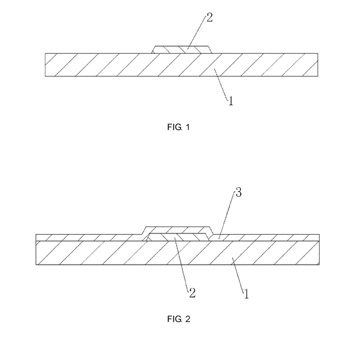
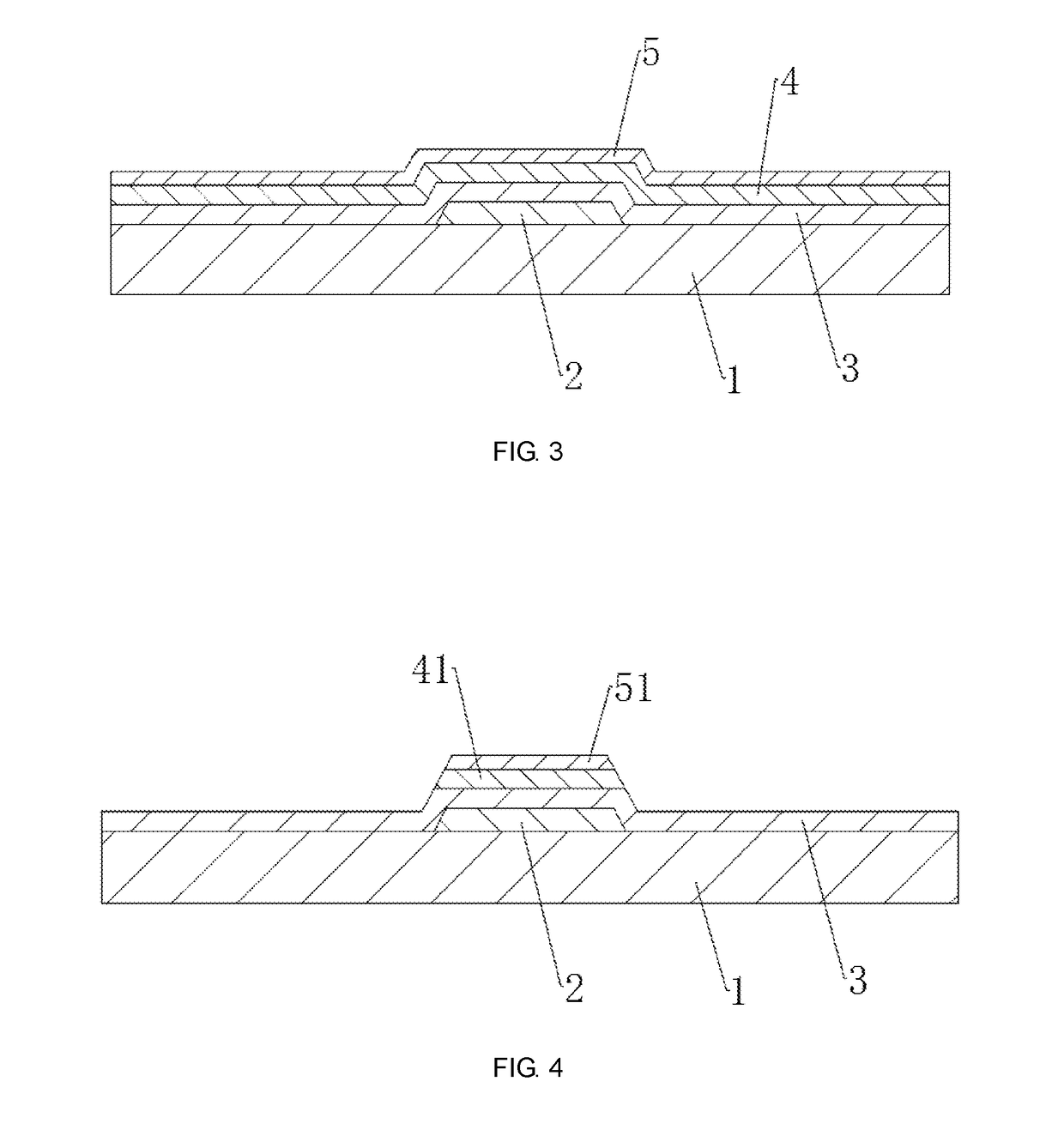
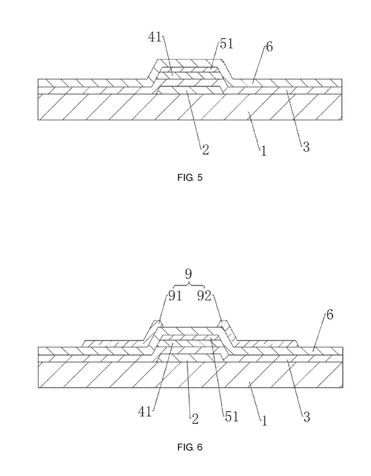
[0040]In order to make those skilled in the art understand the technical solutions of present disclosure better, clear and complete, description of the technical solutions of present disclosure will be illustrated, which combined with the drawings of embodiments in present disclosure. Apparently, described embodiments are merely a portion of embodiments of present disclosure, rather than all of the embodiments. Base on the embodiments of present disclosure, all other embodiments obtained by those skilled in the art without creative work are considered to be encompassed within the scope of the present disclosure.

[0041]Besides, the following descriptions for the respective embodiments are specific embodiments capable of being implemented for illustrations of the present invention with referring to appended figures. For example, the terms of “up”, “down”, “front”, “rear”, “left”, “right”, “interior”, “exterior”, “side”, etcetera are merely directions of referring to appended figures. T...


PUM


Abstract

The present disclosure discloses a method for manufacturing an array substrate comprising: forming a gate electrode on a substrate; forming a gate insulating layer on one side of the substrate facing the gate electrode, the gate insulating layer covering the gate electrode; depositing an indium gallium zinc tin oxide layer and an indium gallium zinc oxide layer on one side of the gate insulating layer away from the gate electrode; patterning the indium gallium zinc oxide layer and the indium gallium zinc tin oxide layer by a first yellow light process to form a protective layer and an active layer, the protective layer covering the active layer; depositing a metal layer on one side of the protective layer away from the active layer; and patterning the metal layer and the protective layer by a second yellow light process to form a source electrode, a drain electrode, and a separation region.

Description

CROSS REFERENCE TO RELATED APPLICATIONS[0001]This application claims priority to Chinese Patent Application No. 201710543887.2, entitled “Manufacturing Method for Array Substrate”, filed on Jul. 5, 2017, the disclosure of which is incorporated herein by reference in its entirety.FIELD OF THE INVENTION[0002]The present disclosure relates to the field of an array substrate, in particular to a method for manufacturing an array substrate.BACKGROUND OF THE INVENTION[0003]With the development of display technology, flat display devices like liquid crystal display (LCD) having advantages of high picture quality, energy saving, slim design and wide range of applications, are widely used in mobile phones, televisions, personal digital assistants, digital cameras, laptops, desktop computers and other consumer electronics products, thereby becoming the predominant display devices.[0004]Most of the liquid crystal display devices on the market are back light type liquid crystal displays, which c...

Claims


Application Information

Patent Timeline
IPC IPC(8): H01L27/12H01L29/24H01L29/786H01L29/66
CPCH01L27/127H01L27/1225H01L27/1288H01L29/24G02F2202/10H01L29/78633H01L29/78618H01L29/66969G02F1/1368H01L29/7869H01L29/78606
Inventor HU, XIAOBO
Owner SHENZHEN CHINA STAR OPTOELECTRONICS TECH CO LTD
Learn More