Color sensing for laser decoating

a laser decoating and color sensing technology, applied in the field of coatings, can solve the problems of inability to strip desired locations as well as undesired locations, and difficulty in maintaining the correspondence between the tv field of view and the laser scanner field,

Active Publication Date: 2009-12-15
GEN LASERTRONICS
View PDF107 Cites 92 Cited by
  • Summary
  • Abstract
  • Description
  • Claims
  • Application Information

AI Technical Summary

Problems solved by technology

The drawback of this approach is the difficulty in maintaining the correspondence between the TV field of view and that of the laser scanner.
Any curvature or movement of the surface causes a mismatch between the camera and laser scanning coordinates.
This results in a failure to strip desired locations as well as stripping undesired locations.

Method used


Image

  • Color sensing for laser decoating
  • Color sensing for laser decoating
  • Color sensing for laser decoating

Examples


Embodiment Construction

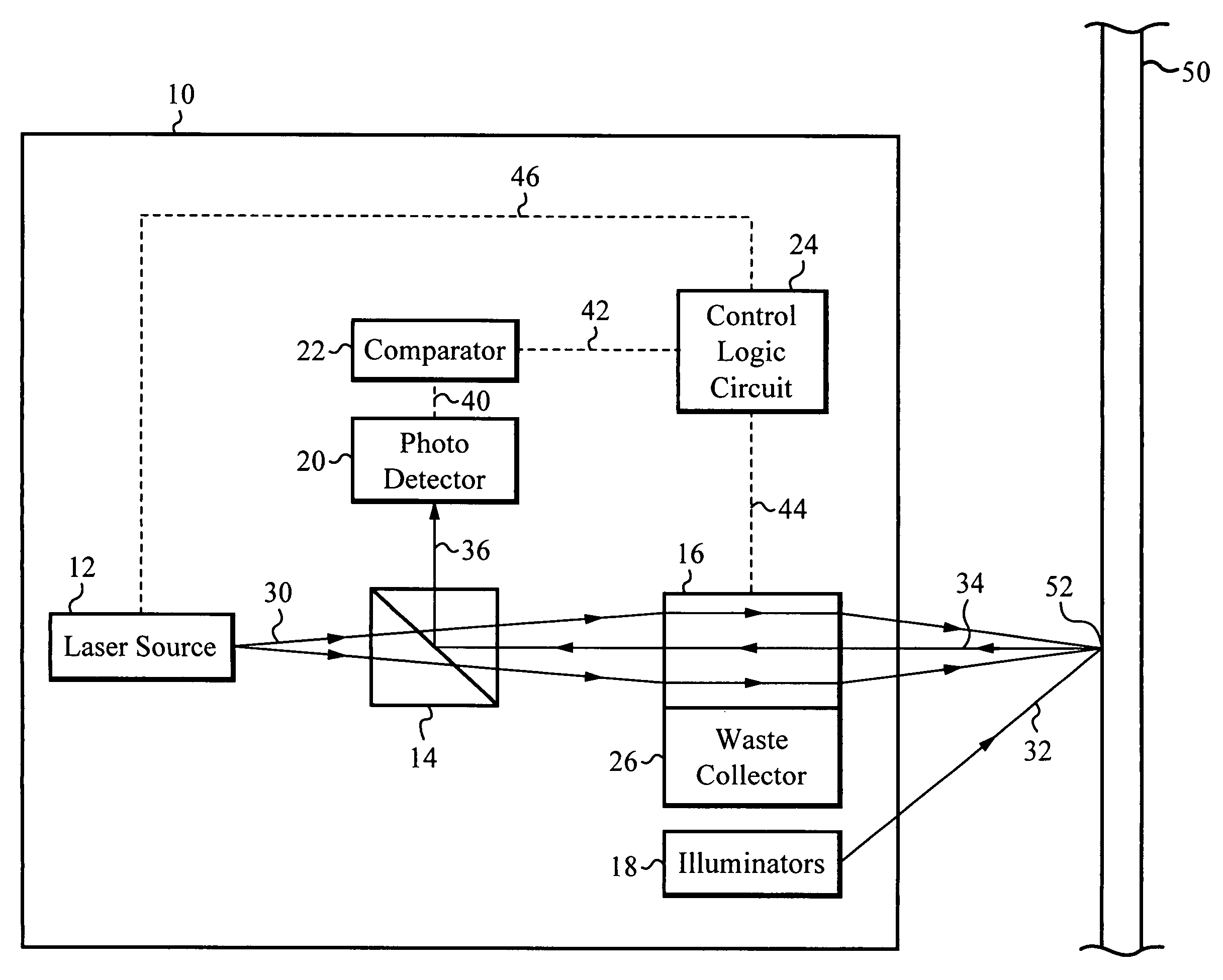
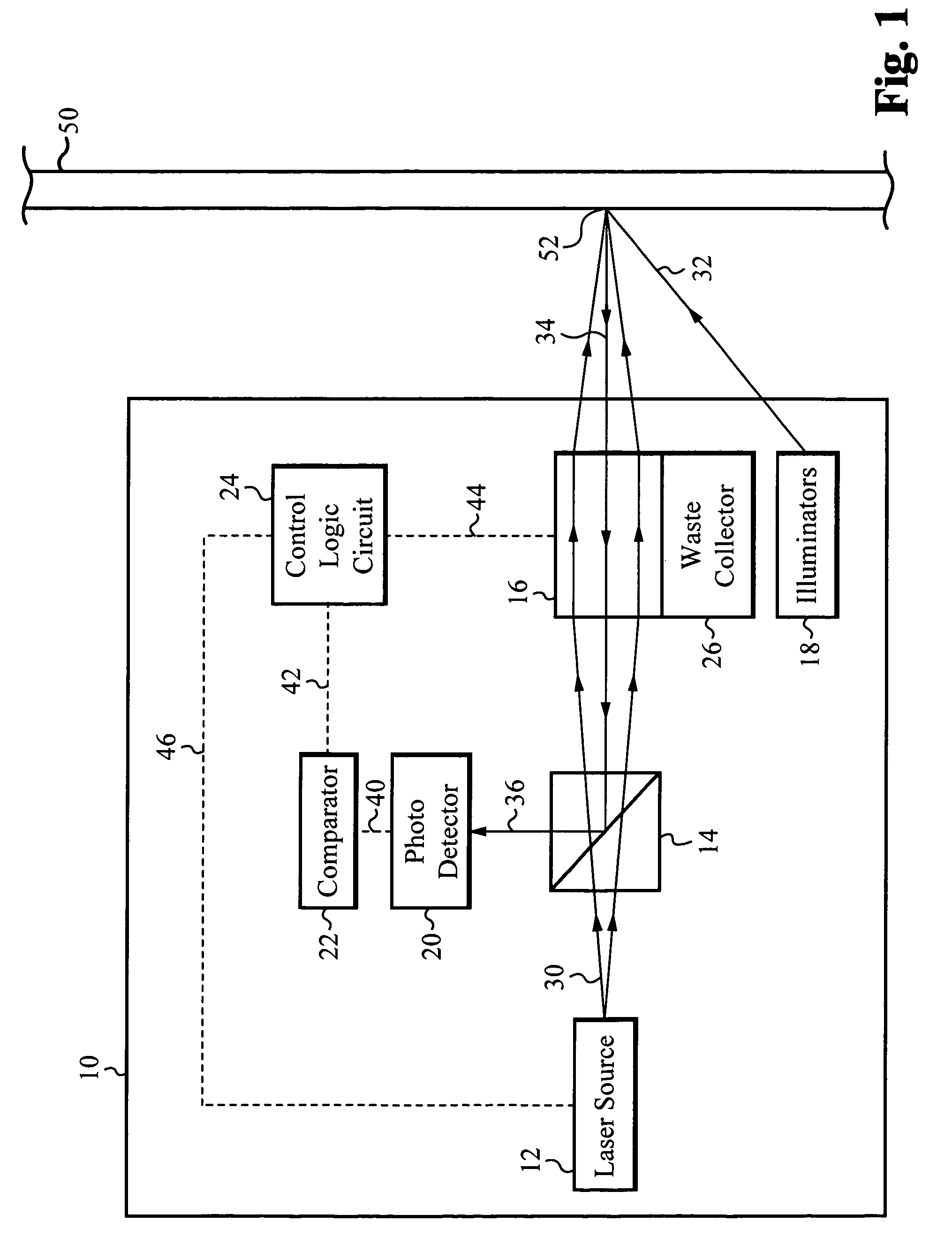
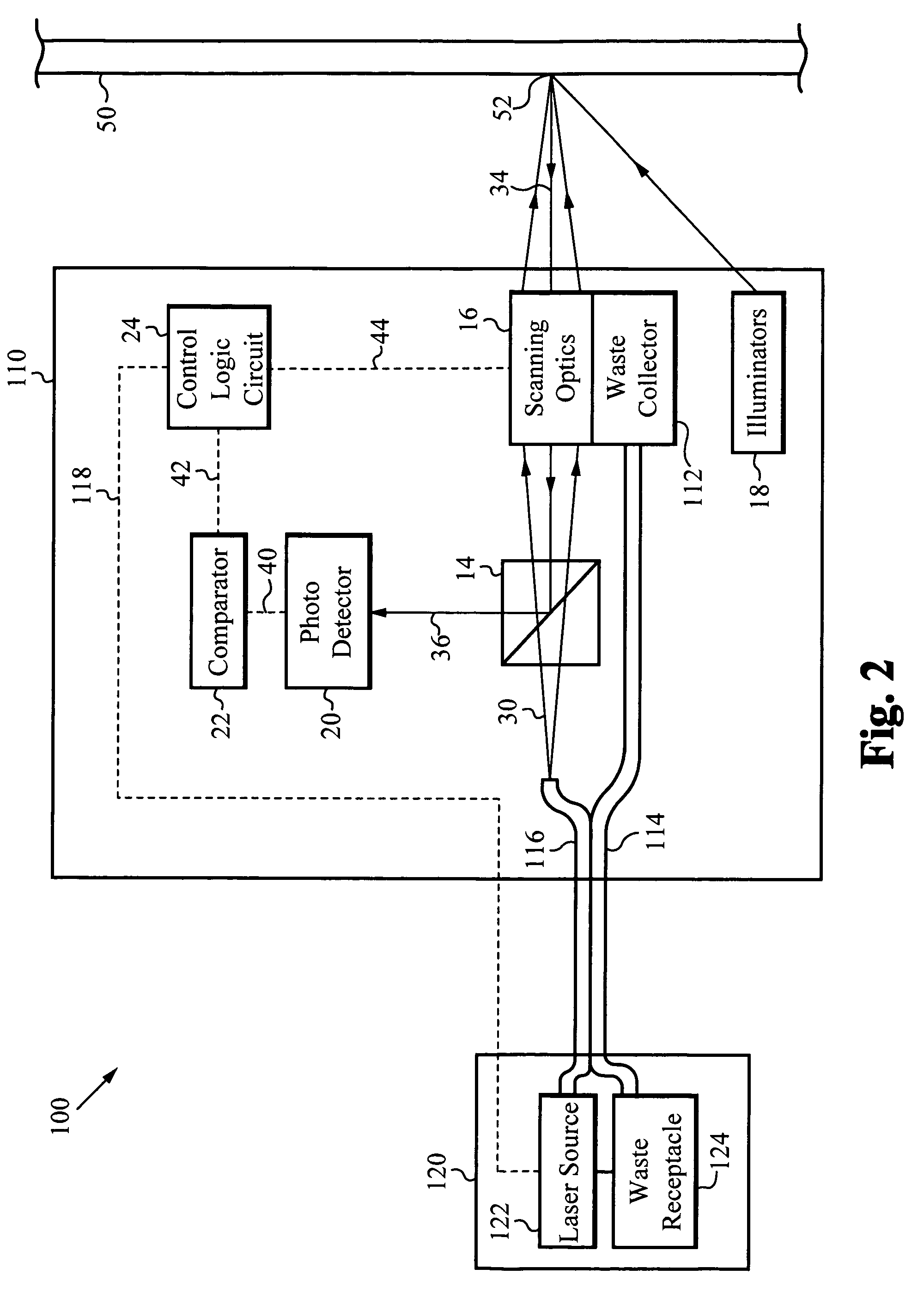
[0022]Embodiments of the present invention are directed to an apparatus for and a method of utilizing a common optics path to provide laser pulses to a coated surface and to direct a light illumination reflected from the coated surface to a photosensitive detector and analyzer. Preferably, the apparatus is an integrated device including a laser source, a beam splitter, scanning optics, a waste removal apparatus, one or more light illuminators, a photosensitive detector, a comparator, and a control logic circuit. Alternatively, the laser source is external to the integrated device and a fiber optic cable is used to connect the laser source to the integrated device.

[0023]The focusing and scanning optics are positioned such that a laser light path is directed to a first position on the coated surface. Immediately prior to firing a laser light pulse on the first position of the coated surface, illuminators provide illumination which is preferably directed to the first position of the co...


PUM

PropertyMeasurementUnit
surface areaaaaaaaaaaa
currentaaaaaaaaaa
wide spectrumaaaaaaaaaa

Abstract

A coating removal apparatus utilizing a common optics path to provide laser pulses to a coated surface and to direct a light illumination reflected from the coated surface to a photosensitive detector and analyzer. The apparatus is an integrated device including a laser source, a beam splitter, scanning optics, a waste removal apparatus, one or more light illuminators, a photosensitive detector, a comparator, and a control logic circuit. Alternatively, the laser source is external to the integrated device and a fiber optic cable is used to connect the laser source to the integrated device.

Description

RELATED APPLICATIONS[0001]This application claims priority of U.S. provisional application, Ser. No. 60 / 535,725, filed Jan. 9, 2004, and entitled “Color Sensing for Laser Decoating,” by the same inventors. This application incorporates U.S. provisional application, Ser. No. 60 / 535,725, filed Jan. 9, 2004, and entitled “Color Sensing for Laser Decoating” in its entirety by reference.FIELD OF THE INVENTION[0002]The invention relates to ablating a coating using a laser. In particular, the invention relates to removing a coating from a surface using a laser and color sensing system.BACKGROUND OF THE INVENTION[0003]Delivery of certain wavelengths of radiant energy is facilitated by transmission along flexible silica fibers. The energy is dispersed from the emitting end of an optical fiber in a widening cone. The energy intensity is generally symmetric about the central fiber axis (e.g., uniformly distributed in azimuth) at the emitting end. The distribution of emitted energy orthogonal t...

Claims


Application Information

Patent Timeline
Patent Type & Authority Patents(United States)
IPC IPC(8): B23K26/36B23K26/03B23K26/08B23K26/16
CPCB23K26/03B23K26/032B23K26/08B23K26/409B23K26/16B23K26/362B23K26/365B23K26/0807B23K26/04B23K26/082B23K26/36B23K26/361B23K26/40B23K2103/172
Inventor THOMAS, JAMES W.WOOL, MITCHELL R.
Owner GEN LASERTRONICS
Why Eureka
Try Eureka