Duplexer for simultaneous transmit and receive radar systems

a radar system and duplexer technology, applied in the field of antennae and receivers, can solve the problems of inability to simultaneously operate, limited technology, and inability to achieve simultaneous operation, and achieve the effects of reducing am/pm sideband residue, reducing noise, and reducing the noise of the noise level

Active Publication Date: 2009-12-15
BAE SYST INFORMATION & ELECTRONICS SYST INTERGRATION INC
View PDF10 Cites 43 Cited by
  • Summary
  • Abstract
  • Description
  • Claims
  • Application Information

AI Technical Summary

Benefits of technology

[0010]Another aspect of the present invention is the presence of a HDR low noise (LN) amplifier between the circulator and the associated directional coupler in the receive path to enable greater sensitivity of operation, and in addition will result in reduced AM / PM sideband residue from the transmit signal.
[0011]Furthermore, where the enhanced duplexer is used in a multiplicity of sites for the antenna elements of a phased array antenna, it is possible to use a wider range of amplifier types for the duplexer having less stringent requirements on the dynamic range performance.
[0014]A further feature of the invention is to use a pair of amplifiers that can readily be designed to track each other in delay characteristics, either by using identical amplifiers in each location or by using similar construction. A fixed path length can be obtained so that the only trim required is amplitude (gain) adjustment of the cancellation path. A tuner can also be placed between the circulator and the antenna element to reduce the leakage signal that is reflected from the antenna.

Problems solved by technology

Heretofore, this technology has been limited by an inability of duplexers in transmit / receive modules to allow simultaneous transmit and receive.
However, it completely cancels the receive signals near the transmit frequency so that simultaneous operation is not possible.
Any losses between the antenna and the receiver (or first low noise amplification device) directly degrade sensitivity by adding thermal noise proportional to the losses directly into the receiver.
In addition to the path losses (such as transmission lines or losses in the coupler), the coupler directly introduces noise into the receiver from the cancellation path and the terminated port of the coupler.

Method used


Image

  • Duplexer for simultaneous transmit and receive radar systems
  • Duplexer for simultaneous transmit and receive radar systems
  • Duplexer for simultaneous transmit and receive radar systems

Examples


Embodiment Construction

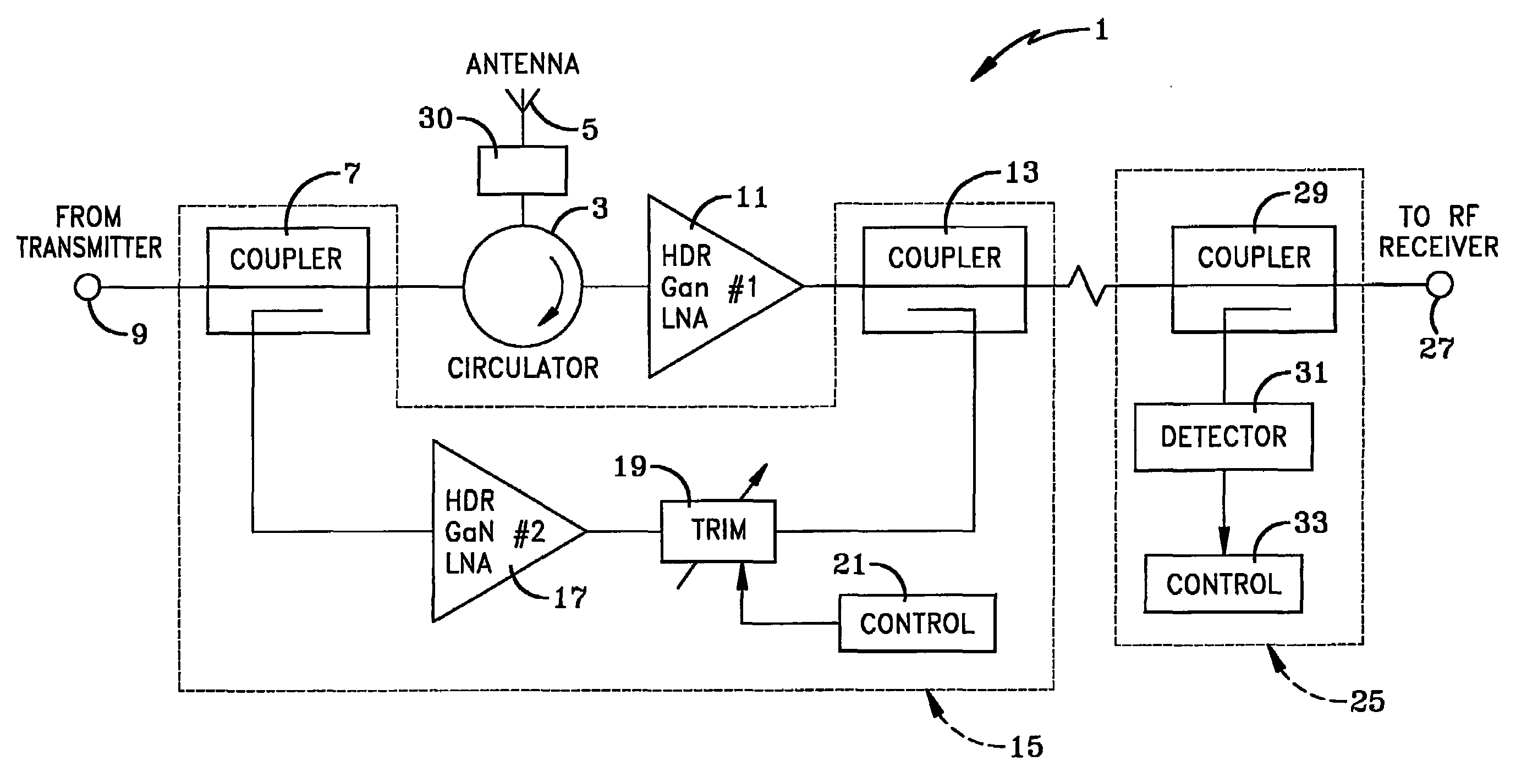
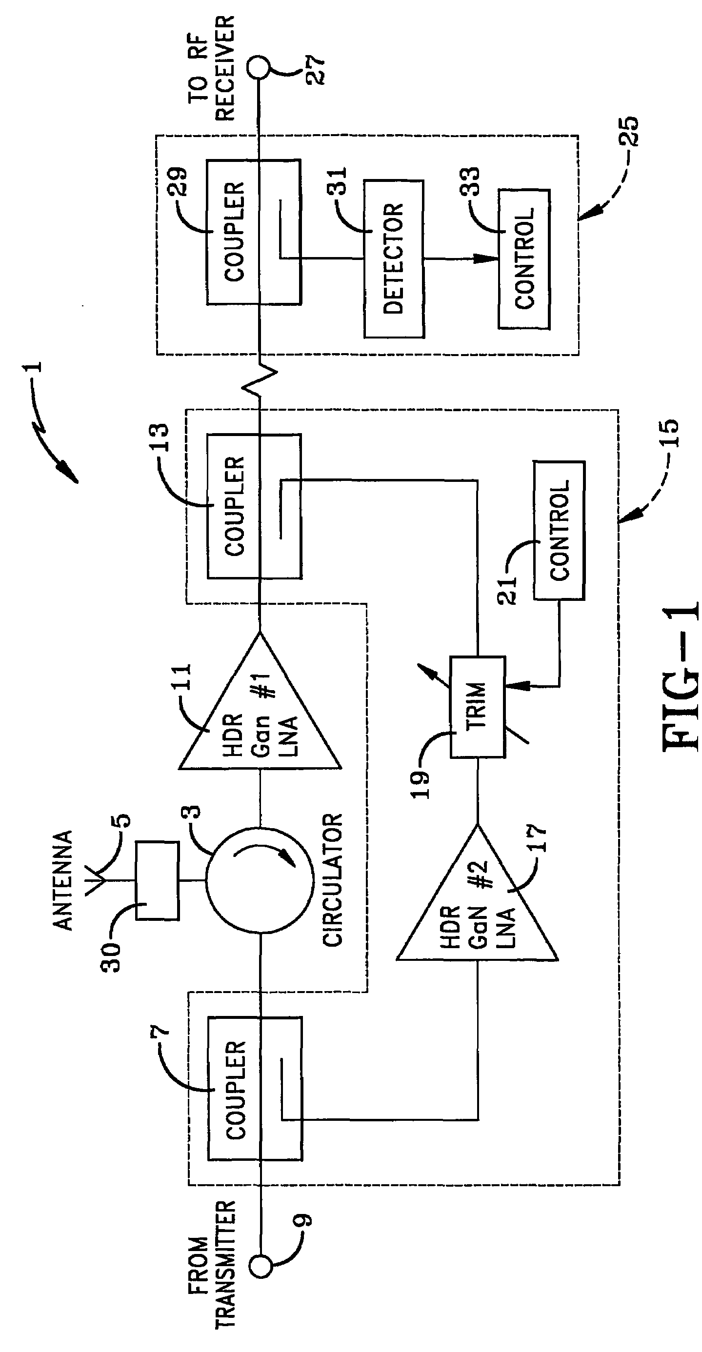
[0021]Up until now the technological challenges of the antenna port duplexer have precluded useful implementations of simultaneous transmit and receive functions for radar applications. Leakage of the transmit signal through the circulator isolation path and from the antenna reflections and mutual coupling paths tends to overload the first amplifier stage in the receive path. In accordance with the present invention, the combination of a pair of high dynamic range, low noise amplifiers, with a novel circuit topology that adaptively cancels leakage signals, provides a solution to this critical problem.

[0022]The adaptive duplexer circuit of the present invention is indicated generally at 1, and is shown in FIG. 1. Duplexer circuit 1 includes a usual circulator 3 which is operationally connected to an antenna 5. A first directional coupler 7 is connected in the feed path between circulator 3 and a transmitter 9. In accordance with one of the main features of the invention, a high dynam...


PUM


Abstract

An enhanced duplexer (1) which includes a combination of high dynamic range (HDR) amplifiers (11, 17) and a naovel signal cancellation circuit topology (15). Return signals from the circulator (3) are fed into the first HDR amplifier (11). A portion of the transmit signal is sampled with a directional coupler (7) and amplified with a second HDR amplifier (17) and then combined with the output of the first HDR amplifier (11) using a second directional coupler (13). The gain and phase of the second io amplifier (17) are adjusted so the leakage signals are canceled (19, 21) to enable a radar system to simultaneously transmit and receive signals to and from an antenna with increased sensitivity of operation.

Description

CROSS REFERENCE TO RELATED APPLICATION[0001]This application claims rights under 35 USC 119(e) from U.S. application Ser. No. 60 / 603,908, filed Aug. 24, 2004; the contents of which are incorporated herein by reference.BACKGROUND OF THE INVENTION[0002]1. Technical Field[0003]The present invention relates to antennae and receivers and more particularly to duplexers used in radar systems for simultaneously transmitting and receiving signals to and from an antenna. Even more particularly, the invention relates to the use of high dynamic range low noise amplifiers in combination with directional couplers of a cancellation circuit to cancel leakage signals in order to provide greater sensitivity of operation of the radar system.[0004]2. Background Information[0005]In radar apparatus, duplexers isolate the receiver from the transmitter while permitting them to share a common antenna. A duplexer is designed for operation in the frequency band used by the receiver and transmitter, and must b...

Claims


Application Information

Patent Timeline
Patent Type & Authority Patents(United States)
IPC IPC(8): G01S13/00
CPCG01S7/038G01S7/034
Inventor MEHARRY, DAVID E.HEDGES, STEPHEN A.
Owner BAE SYST INFORMATION & ELECTRONICS SYST INTERGRATION INC
Why Eureka
Try Eureka