Navigation system and navigation method

a navigation system and navigation method technology, applied in the direction of instruments, micro-instruction address formation, static indicating devices, etc., can solve the problems of additional power consumption and noise, limitation of electrical speed of optical sensors, optical mouse cannot trace the movement of optical mouse, etc., to achieve correct detection movement and increase sampling speed

Inactive Publication Date: 2009-12-15
SAMSUNG ELECTRO MECHANICS CO LTD +1
View PDF9 Cites 11 Cited by
  • Summary
  • Abstract
  • Description
  • Claims
  • Application Information

AI Technical Summary

Benefits of technology

[0008]It is a feature of an embodiment of the present invention to provide a navigation system and a navigation method capable of correctly detecting movement of an optical system without increasing sampling speed when an optical mouse moves fast.
[0010]It is a feature of an embodiment of the present invention to provide a navigation system that consumes a small amount of power and has good noise reduction characteristic.

Problems solved by technology

Since such conventional pixel mapping is targeted to detect movement or displacement within one pixel in nine directions, if an optical mouse moves by more than one pixel in one sampling period, the optical mouse cannot trace the movement of the optical mouse and therefore generates an error.
However, there is a limitation to increase electrical speed of an optical sensor.
This conventional method is disadvantageous in additional power consumption and noise increase.
Further, the conventional method is disadvantageous in that the conventional navigation system consumes a great amount of power and causes a big noise because input frame selection period is maintained constant even if movement speed of an optical mouse is changed.

Method used


Image

  • Navigation system and navigation method
  • Navigation system and navigation method
  • Navigation system and navigation method

Examples


Embodiment Construction

[0026]Korean Patent Application No. 2002-20132 and 2002-20133, filed on Apr. 12, 2002, and entitled: “Navigation Method and Navigation System,” is incorporated by reference herein in its entirety.

[0027]Hereinafter, the present invention will be described in detail by describing preferred embodiments of the present invention with reference to the accompanying drawings. Like reference numerals refer to like elements throughout the drawings.

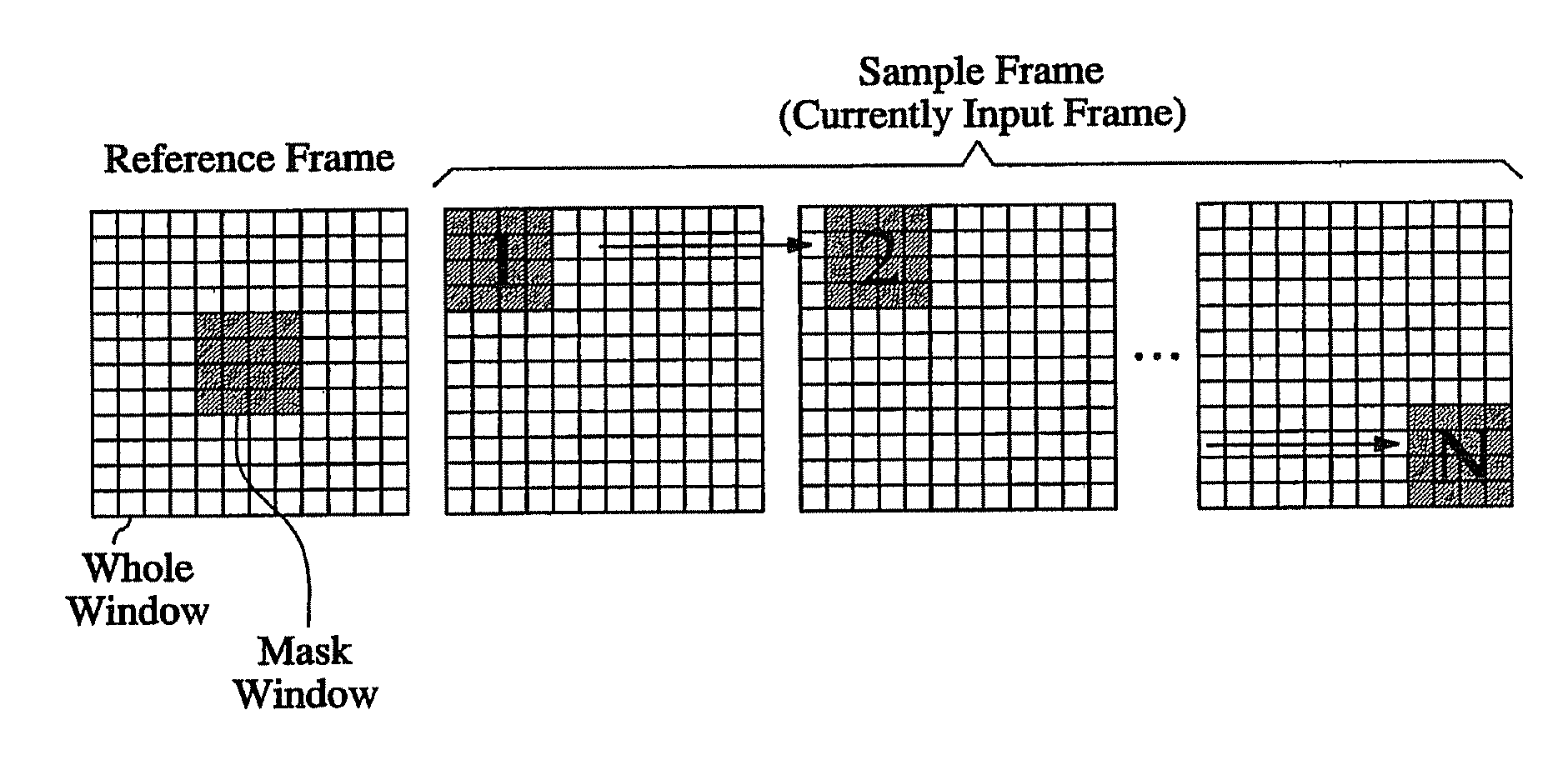
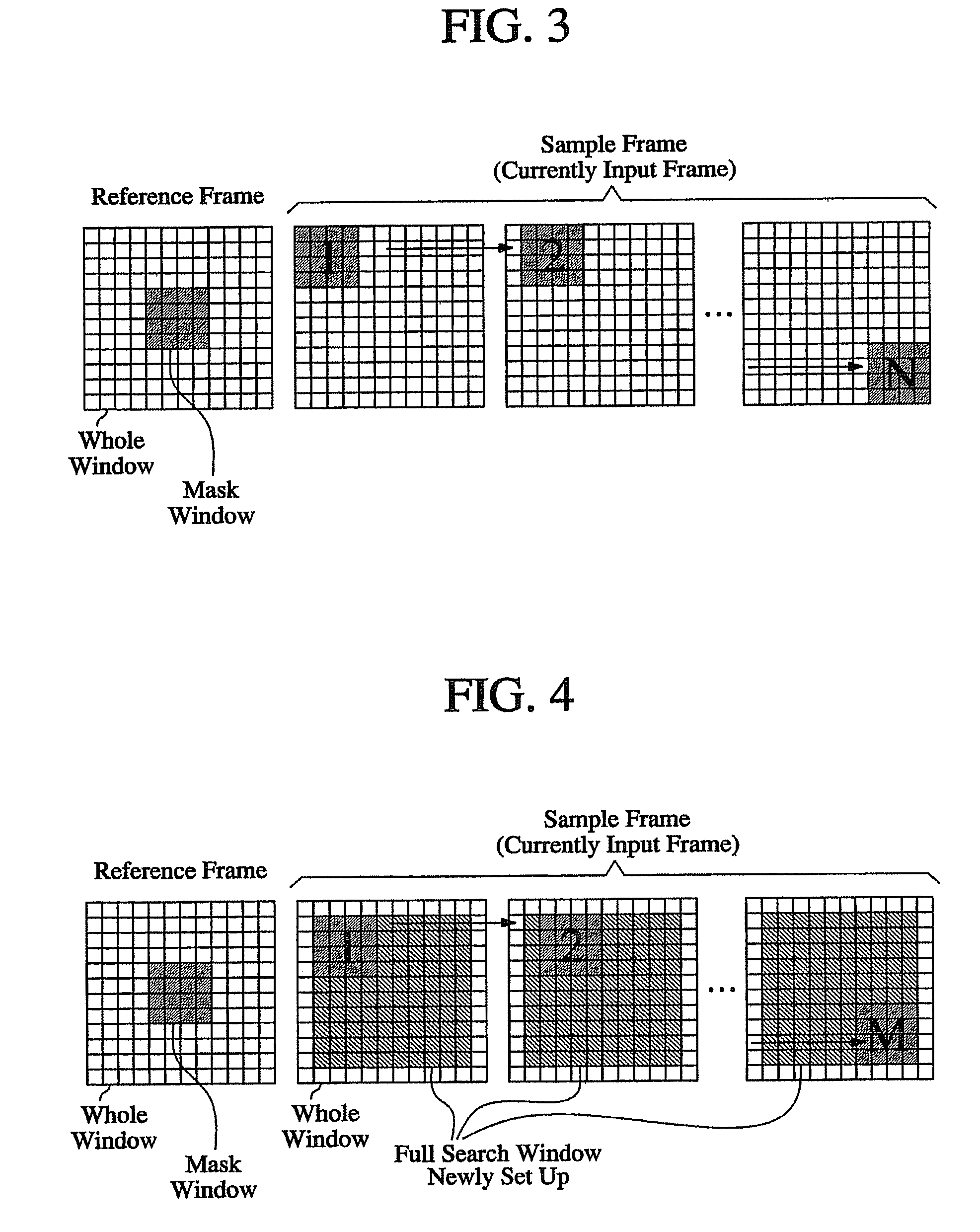
[0028]FIG. 3 illustrates a pixel mapping method for obtaining correlation values between a reference frame and a current input frame.

[0029]Movement of an optical mouse is detected by comparing pixels on a current input frame and pixels on a subsequent input frame, wherein the input frames are input at predetermined intervals. A preceding input frame serves as a reference frame and a mask window is set on a portion of the reference frame. Then, the mask window and a subsequent input frame are compared with each other. At this time, a full search comp...


PUM


Abstract

Disclosed are a navigation system and a navigation method, wherein the navigation method comprises the steps of sequentially providing image frames containing navigation information and generating electric signals corresponding to a position of an optical sensor, storing a first image frame into a reference frame memory as a reference frame, storing an input image frame subsequent to the first image frame into an input frame memory as a current input frame, setting a mask window having a predetermined size on the reference frame, obtaining correlation values over all the pixels on the current input frame by a full search comparison method, by moving the mask window on the current input frame pixel by pixel, calculating X-axis and Y-axis displacements of a pixel having the greatest correlation value of all the pixels, and updating the reference frame using the current input frame stored in the input frame memory.The navigation system and the navigation method in accordance with the present invention may change input frame selection period based on movement speed of an optical mouse, so that it is possible to detect movement of an optical mouse without changing sampling speed of an optical sensor even when an optical mouse moves fast. Further, the navigation system and the navigation method in accordance with the present invention may consume low power in comparison with a conventional navigation system and method, and reduce noises existed in an optical mouse.

Description

BACKGROUND OF THE INVENTION[0001]1. Field of the Invention[0002]The present invention relates to a navigation system and a navigation method, and more particularly to a navigation system and a navigation method capable of changing input frame selection period based on movement speed of an optical mouse, wherein pixel mapping is performed by comparing all the pixels in a current input frame with all the pixels in a reference frame.[0003]2. Description of the Related Art[0004]The operation of an optical mouse is will be described below with reference to FIG. 1. Referring to FIG. 1, light beams 7 emitted from an illuminating source 8 are incident onto a worktable and are reflected at the surface 2 of the worktable. The reflected light beams 6 pass through a lens 5 and are incident onto an optical sensor implemented by a semiconductor chip. The optical sensor 3 continuously captures images formed on the surface of the worktable and then the captured images are stored in a memory device ...

Claims


Application Information

Patent Timeline
Patent Type & Authority Patents(United States)
IPC IPC(8): G09G5/00G06F3/03G06F3/033G06F9/26G06F9/32G06F12/00
CPCG06F3/0317
Inventor LEE, BANG WONKWAK, JONG TAEK
Owner SAMSUNG ELECTRO MECHANICS CO LTD
Why Eureka
Try Eureka