Polycrystalline diamond compact (PDC) cutting element having multiple catalytic elements

a technology of diamond compact and cutting element, applied in the direction of drill bits, metal-working apparatus, earth-moving drilling and mining, etc., can solve the problems of high stress, premature failure of compact, diamond-to-diamond bond fracture, etc., and achieve the effect of improving thermal stability

Inactive Publication Date: 2009-12-22
US SYNTHETIC CORP
View PDF85 Cites 190 Cited by
  • Summary
  • Abstract
  • Description
  • Claims
  • Application Information

AI Technical Summary

Benefits of technology

[0062]It is desirable to provide improved thermal stability in polycrystalline diamond compacts (PDC). It is particularly desirable to provide such improved stability by incorporating in the design of the PDC two or more catalytic elements, at least one of which is a thermally stable catalytic element and which is incorporated in and / or within the cutting surface.

Problems solved by technology

Generally, these prior devices do not incorporate a thermally stable catalytic element in the region adjacent to the cutting surface, that therefore prior PDC devices tend to have a mismatch in thermal expansion that can cause the interstitial metal to exert a high stress on the diamond lattice, which in turn can lead to fracture of the diamond-to-diamond bonds and subsequent premature failure of the compact.
Further, prior PDC devices tend to incorporate a non-thermally stable catalytic element that readily dissolves carbon from the diamond surface at elevated temperatures, thereby, leading to the conversion of diamond to graphite, which in turn leads to premature failure of the compact.
These high temperatures can cause premature failure of the tool via several mechanisms, two of which are graphitization of the polycrystalline diamond in contact with the interstitial metallic catalyst and thermal expansion of the interstitial metallic catalyst.
The mismatch in thermal expansion causes the interstitial metal to exert a high stress on the diamond lattice.
These stresses can lead to a fracture of diamond-to-diamond bonds at or above about 700° C. and subsequent premature failure of the compact.

Method used


Image

  • Polycrystalline diamond compact (PDC) cutting element having multiple catalytic elements
  • Polycrystalline diamond compact (PDC) cutting element having multiple catalytic elements
  • Polycrystalline diamond compact (PDC) cutting element having multiple catalytic elements

Examples


Embodiment Construction

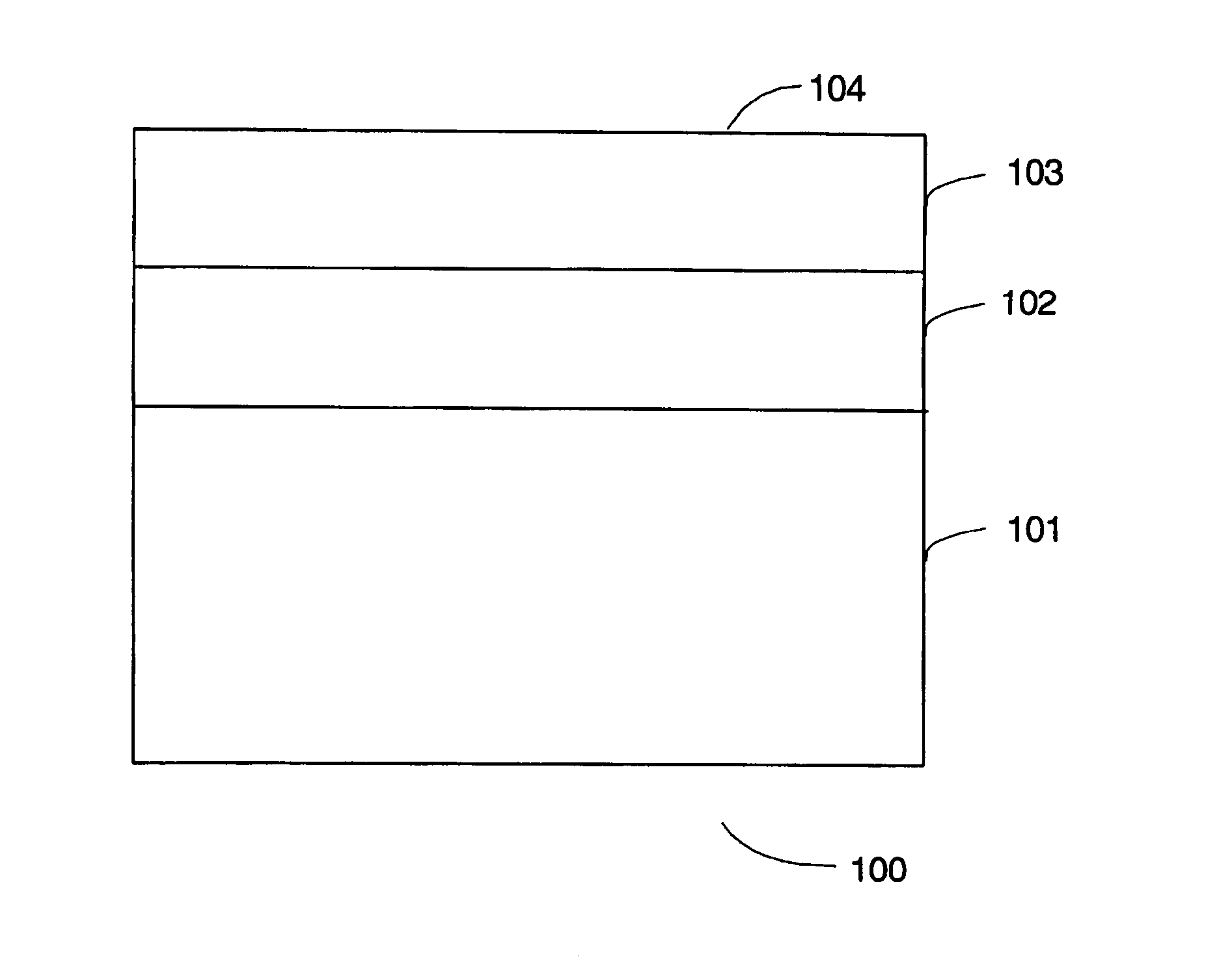
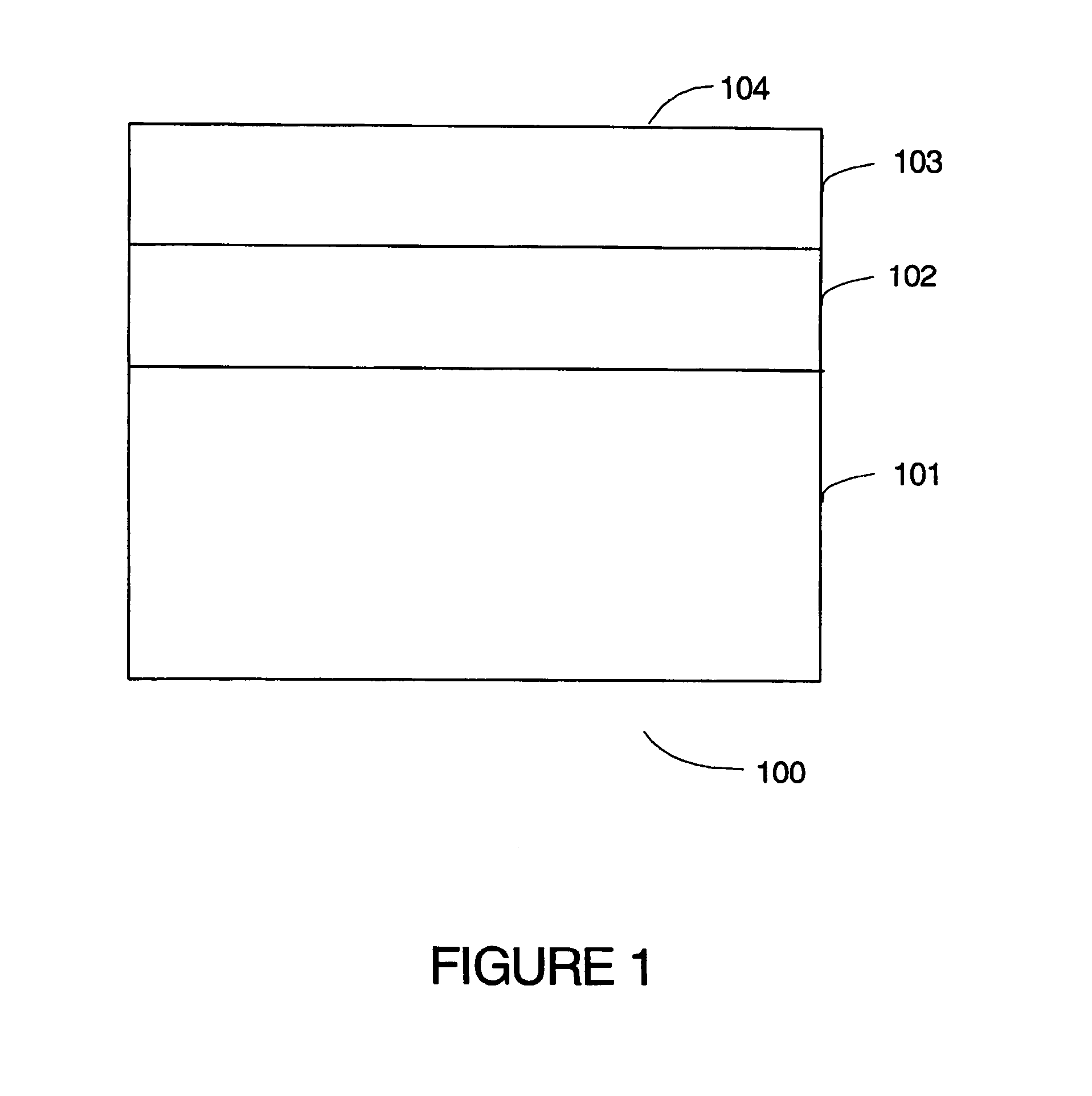
[0101]The polycrystalline diamond compact (PDC) of this invention is manufactured so as to incorporate two or more different catalytic elements. A traditional metallic catalytic element is used in a region or volume of the polycrystalline diamond layer adjacent to the cemented carbide substrate. Generally, this metallic catalyst is readily supplied by the substrate during the high temperature / high pressure (HT / HP) sintering process step, where a strong metallurgical bond is created between the polycrystalline diamond layer and the substrate. One of the important and novel features of this invention is the incorporation and use of a thermally stable non-metallic catalytic element in the region or volume of the polycrystalline diamond layer adjacent to the working or cutting surface, in addition to the metallic catalyst provided in the volume of the polycrystalline diamond layer adjacent to the cemented carbide substrate. For the purposes of this disclosure, polycrystalline diamond sh...


PUM

PropertyMeasurementUnit
temperatureaaaaaaaaaa
volumeaaaaaaaaaa
temperatureaaaaaaaaaa

Abstract

A polycrystalline diamond compact useful for wear, cutting, drilling, drawing and like applications is provided with a first diamond region remote from the working surface which has a metallic catalyzing material and a second diamond region adjacent to or including the working surface containing a non-metallic catalyst and the method of making such a compact is provided. This compact is particularly useful in high temperature operations, such as hard rock drilling because of the improved thermal stability at the working surface.

Description

BACKGROUND OF INVENTION[0001]1. Field of the Invention[0002]This invention relates to superhard polycrystalline cutting elements used for wear, drawing and other tool applications where superhard properties are useful. More specifically, this invention relates to such superhard polycrystalline cutting elements that make use of polycrystalline diamond regions for the cutting or wear surface.[0003]2. Description of Related Art[0004]A wide variety of polycrystalline diamond compacts (PDC) are well known in the art. Generally, these prior devices do not incorporate a thermally stable catalytic element in the region adjacent to the cutting surface, that therefore prior PDC devices tend to have a mismatch in thermal expansion that can cause the interstitial metal to exert a high stress on the diamond lattice, which in turn can lead to fracture of the diamond-to-diamond bonds and subsequent premature failure of the compact. Further, prior PDC devices tend to incorporate a non-thermally sta...

Claims


Application Information

Patent Timeline
Patent Type & Authority Patents(United States)
IPC IPC(8): B32B9/00
CPCB32B9/00C04B35/52C04B35/6303C04B35/645C04B2235/3203C04B2235/3208C04B2235/44C04B2235/3256C04B2235/3843C04B2235/3201C04B2235/3225Y10T407/27C04B2235/3206C04B2235/3821C04B2235/442C04B2235/448C04B2235/3274C04B2235/427C04B2235/3213C04B2235/3272C04B2235/3427C04B2235/421C04B2235/3234B24D3/10B24D3/18E21B10/55E21B10/567
Inventor BERTAGNOLLI, KENNETH E.VAIL, MICHAEL A.
Owner US SYNTHETIC CORP
Why Eureka
Try Eureka