Bone removal device

a bone graft and implant technology, applied in the field of bone grafting devices, can solve the problems of loss of both support areas, compromise the quality of the fusion construct, and it is not possible to shape such grafts, and achieve the effect of maximum stability of the graft/implan

Inactive Publication Date: 2009-12-22
WARSAW ORTHOPEDIC INC
View PDF26 Cites 12 Cited by
  • Summary
  • Abstract
  • Description
  • Claims
  • Application Information

AI Technical Summary

Benefits of technology

[0026]The present invention is directed to an apparatus and method for use in spinal surgery for creating a space of selected shape and dimensions across the disc space between two adjacent vertebrae of the spine. The present invention comprises an integrated system of instrumentation and a surgical method that is capable of placing the adjacent vertebrae to be operated upon in proper angular relationship to each other, of locking the vertebrae in that position, of simultaneously preparing both vertebral endplates for the procedure, be it fusion or disc replacement, and specifically the creation of a space of a known shape and dimensions. The foregoing is achieved by the use of a power milling apparatus such that all free hand motions are eliminated and the site size, shape, and configuration, as well as the extent of vertebral endplate resection are made predictable, precise and reproducible. The instrumentation of the present invention allows for the safe controlled and protected preparation of the disc space to the optimal depth and width. The present invention allows for implant(s) or bone grafts to be placed onto the area of dense bone at the posterior lateral aspects of the disc space. The present invention allows for the maximum stability of the graft / implant, as well as the construct, by providing for the greatest possible interface surface area and congruency between the graft / implant and each of the adjacent vertebrae.
[0027]The present invention further provides for increased stability by creating butted corners, posterolaterally, into which the graft / implant may be fitted which corners prevent further movement of the graft / implant either posteriorly or to either side of the created space. The present invention is capable of the uniform preparation (scraping) of the central portion of the vertebral endplate otherwise leaving that structure intact, if so desired. The present invention makes possible the preparation of the disc space to be prepared in anatomical angular conformation, and the disc space can be formed so as to correspond to the known shape of the graft / implant to be utilized.
[0043]In the alternative, the surgical method of the present invention may be performed by utilizing a separable milling block having a separable member with bilateral, lateral distractor elements such that the distractor elements are left in place in the disc space while steps 9-12 above of the method are performed. However, in this instance no distraction would be necessary in step 12 as the distractor elements remain in place while the appropriate implant(s) are inserted into the prepared space and the distractor elements are subsequently removed. The placement of bilateral distractor elements also provides a safety means for preventing the bone removal means and implant from exiting from the sides of the disc space and out of the spine.OBJECTS OF THE PRESENT INVENTION
[0044]It is an object of the present invention to provide for a surgical method and instrument means for performing interbody spinal fusion or in the alternative of inserting an “artificial disc implant” for the purpose of maximizing the width and optimizing the depth of the disc and the bone removed from front to back, or back to front, from the vertebral endplates adjacent the disc space to be fused or implanted while confining such bone resection safely within the lateral, anterior (front) and posterior (back) limits of the disc space.
[0045]It is another object of the present invention to provide for a surgical method and instrument means for performing interbody spinal fusion or “artificial disc” implantation that provides for the rapid creation of both a known surface contour of each of the vertebral endplates adjacent a disc space as well as a known and reproducible shape of the fusion or implantation site itself.
[0046]It is another object of the present invention to provide for a surgical method and instrument means for performing interbody spinal fusion that allows for the utilization of a larger interbody spinal fusion implant(s) than was possible with the prior art, such an implant having the capacity for providing increased amounts of osteogenic material, increased surface area, increased area of contact, increased stability and the ability to provide for greater support through the fusion area.

Problems solved by technology

Even for the most skilled surgeon, it is not possible to shape such grafts to precisely fit the complex contours of the vertebral endplates adjacent the disc space.
This further compromises the quality of the fusion construct in that the area of contact between the vertebrae and the graft is suboptimal with a loss of both support area and correspondingly, graft and construct stability.
Further factors tending to limit the dimensions of the graft to less than that of the disc space include, for example in the cervical spine, the danger of the graft accidentally escaping the disc space laterally (to the side), damaging the vertebral arteries and causing a cerebral infarct and the danger of penetrating posteriorly (toward the back) and injuring the spinal cord causing paralysis.
Furthermore, the previously described pillars of dense bone projecting from the overall plane of the vertebral endplates in the posterolateral portions of the disc space and commonly known as either uncinate processes or the joints of Luschka, tend to block the lateral and posterior placement of the graft(s) and tend to confine and limit the placement of the graft(s) to the anterior and central portions of the disc space.
When lordosis is the result of a generally wedge shaped disc, it has generally proven difficult to reliably restore that overall wedged shape to the disc space itself for the purpose of fusing the adjacent vertebrae with precisely the correct amount of lordosis.

Method used


Image

  • Bone removal device
  • Bone removal device
  • Bone removal device

Examples


Embodiment Construction

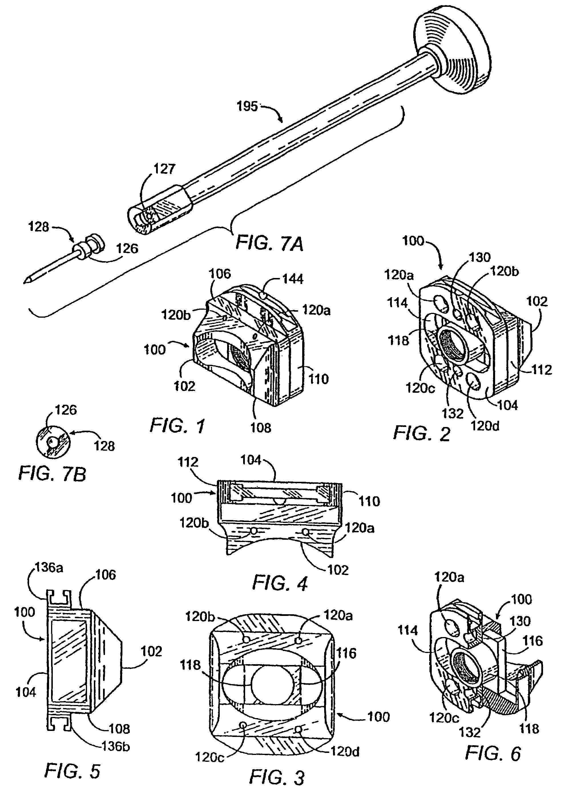
[0126]Referring to FIGS. 1-6, the instrumentation of the present invention comprises a milling block, generally referred to by the numeral 100. The milling block 100 has an overall generally rectangular configuration having a front face 102, an opposite rear face 104, a top side 106, a bottom side 108 and left and right sides 110 and 112, respectively. The front face 102 comprises a surface having a concave configuration that conforms to the natural curvature of the anterior aspect of a segment of the human spinal column and permits the placement of the milling block 100 in close proximity to the anterior aspect of the spinal column. The milling block 100 comprises a central aperture 114 through the center of the milling block 100. The aperture 114 is preferably oblong-shaped, having an approximate width of 18-30 mm for use in the cervical spine, 30-50 mm for use in the lumbar spine, and if the milling block 100 is used on the left and right sides of the mid sagittal axis of a lumba...


PUM


Abstract

An apparatus and method for placing adjacent vertebrae at a fixed distance and angular relationship relative to each other, fixing said vertebrae in said position by use of a milling block engaging each of said adjacent vertebrae and then using a milling means, the depth, length and excursion of which from side to side are controlled by said apparatus to machine out a defined thickness of bone and a space of defined length, height, width and shape in preparation for receiving an interbody spinal implant or graft of known size and configuration are disclosed.

Description

[0001]The present application is a continuation of Ser. No. 10 / 090,506, filed Feb. 27, 2002 now U.S. Pat. No. 7,083,623; which is a continuation of application Ser. No. 09 / 734,303, filed Dec. 12, 2000, now U.S. Pat. No. 6,440,139; which is a continuation of application Ser. No. 08 / 688,758, filed Jul. 31, 1996, now U.S. Pat. No. 6,159,214; all of which are incorporated herein by reference.BACKGROUND OF THE INVENTION[0002]Spinal fusion is defined as the joining together of two or more adjacent vertebrae through a bridge of bone for the purpose of eliminating motion between those vertebrae. One specific type of spinal fusion is known to those skilled in the art as interbody fusion and consists of fusing the adjacent vertebrae through the disc space (the space previously occupied by the spinal disc interposed between the adjacent vertebral bodies). When such a procedure is performed from the anterior aspect of the spine (from the front) that procedure is known as anterior interbody fusi...

Claims


Application Information

Patent Timeline
Patent Type & Authority Patents(United States)
IPC IPC(8): A61B17/60A61B17/56A61B17/02A61B17/16A61B17/17A61F2/00A61F2/44
CPCA61B17/025A61B17/1671A61B17/1757A61B2017/0256A61F2230/0019A61F2/442A61F2/4455A61F2002/30153A61B2017/1602
Inventor MICHELSON, GARY K.
Owner WARSAW ORTHOPEDIC INC
Why Eureka
Try Eureka