Plasma generating electrode, plasma generation device, and exhaust gas purifying device

a plasma generation and purification device technology, applied in gas-filled discharge tubes, energy-based chemical/physical/physico-chemical processes, machines/engines, etc., can solve the problem that uniform plasma cannot be generated over the entire electrode, and achieve uniform and stable plasma, reliably purifying exhaust gas, and low power consumption

Inactive Publication Date: 2009-12-22
NGK INSULATORS LTD +1
View PDF9 Cites 6 Cited by
  • Summary
  • Abstract
  • Description
  • Claims
  • Application Information

AI Technical Summary

Benefits of technology

[0005]The present invention has been achieved in view of the above-described problem, and provides a plasma generating electrode and a plasma generation device capable of generating uniform and stable plasma at low power consumption. The invention also provides an exhaust gas purifying device which includes the above plasma generation device and a catalyst and can reliably purify exhaust gas.

Problems solved by technology

However, since such a plasma generating electrode used to generate plasma causes a local point discharge to occur between a pair of electrodes disposed opposite to each other, there arises a problem that uniform plasma cannot be generated over the entire electrode.

Method used


Image

  • Plasma generating electrode, plasma generation device, and exhaust gas purifying device
  • Plasma generating electrode, plasma generation device, and exhaust gas purifying device
  • Plasma generating electrode, plasma generation device, and exhaust gas purifying device

Examples


example 1

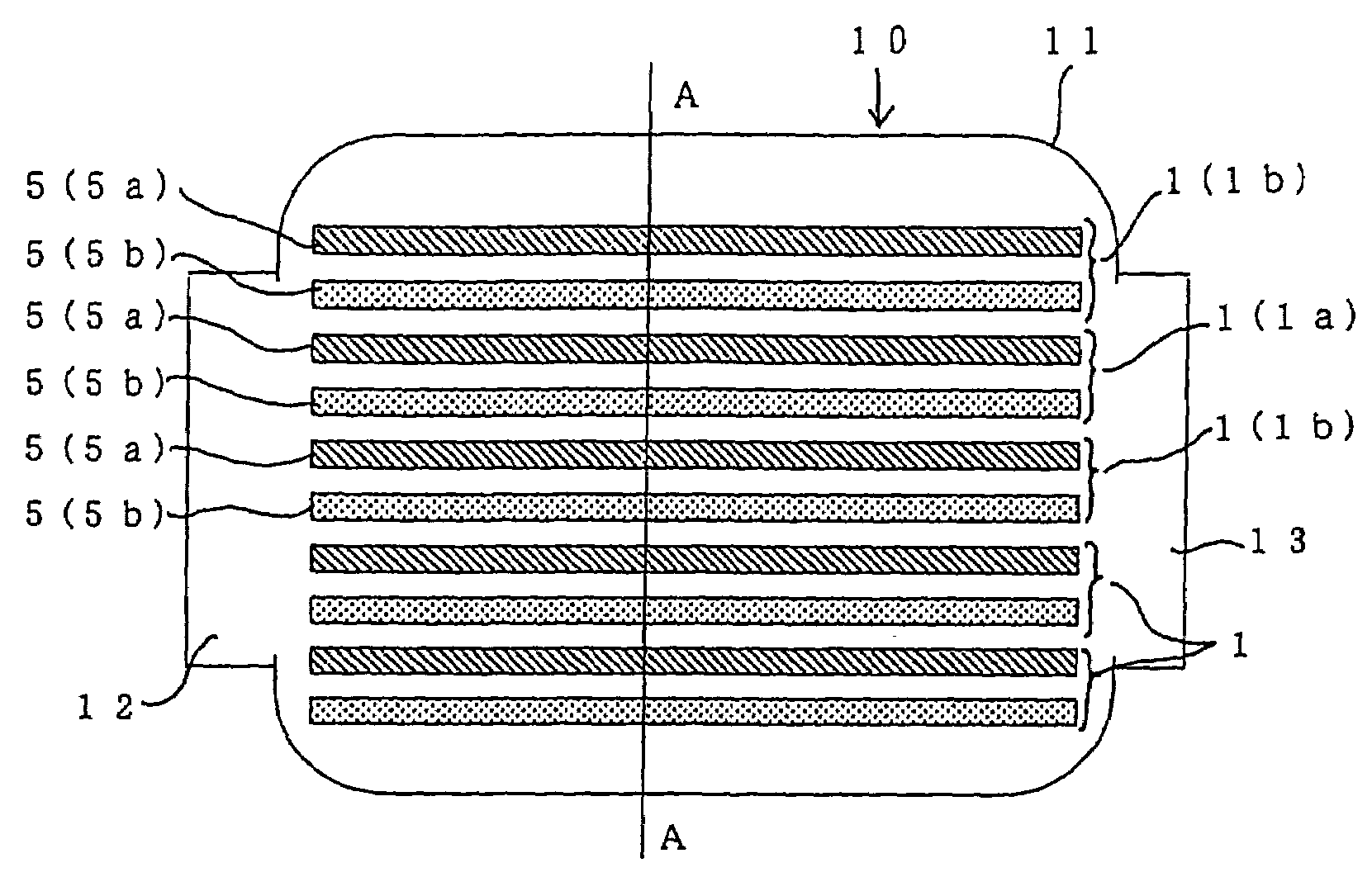
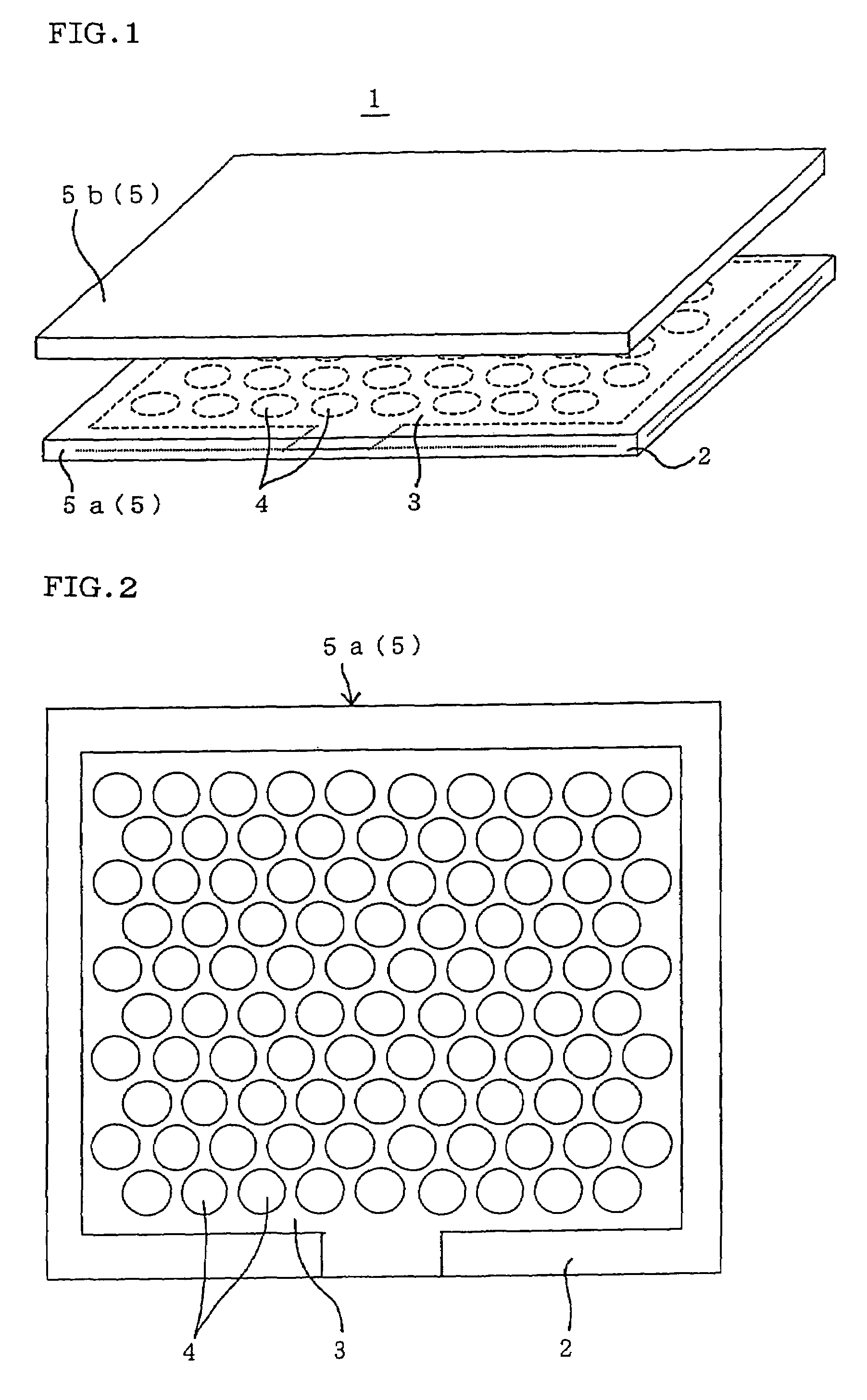
[0076]A plasma generation device including the plasma generating electrode 1 as shown in FIG. 1 was manufactured. The plasma generating electrode was manufactured by disposing two electrodes opposite to each other at a distance of 1 mm, each of the electrodes including a plate-like ceramic body as a dielectric formed of an alumina tape, and a conductive film disposed inside the ceramic plate and having through-holes formed through the conductive film in its thickness direction and having a circular cross-sectional shape along a plane perpendicular to the thickness direction. One of the pair of electrodes of the plasma generating electrode was used as a voltage application side, and the other was used as a grounding side.

[0077]The ceramic plate had a length of 50 mm, a width of 90 mm, and a thickness of 1 mm. The conductive film had a length of 40 mm, a width of 80 mm, and a thickness of 20 μm. The through-holes had a diameter of 3 mm and were equally formed so that the center-to-cen...

example 2

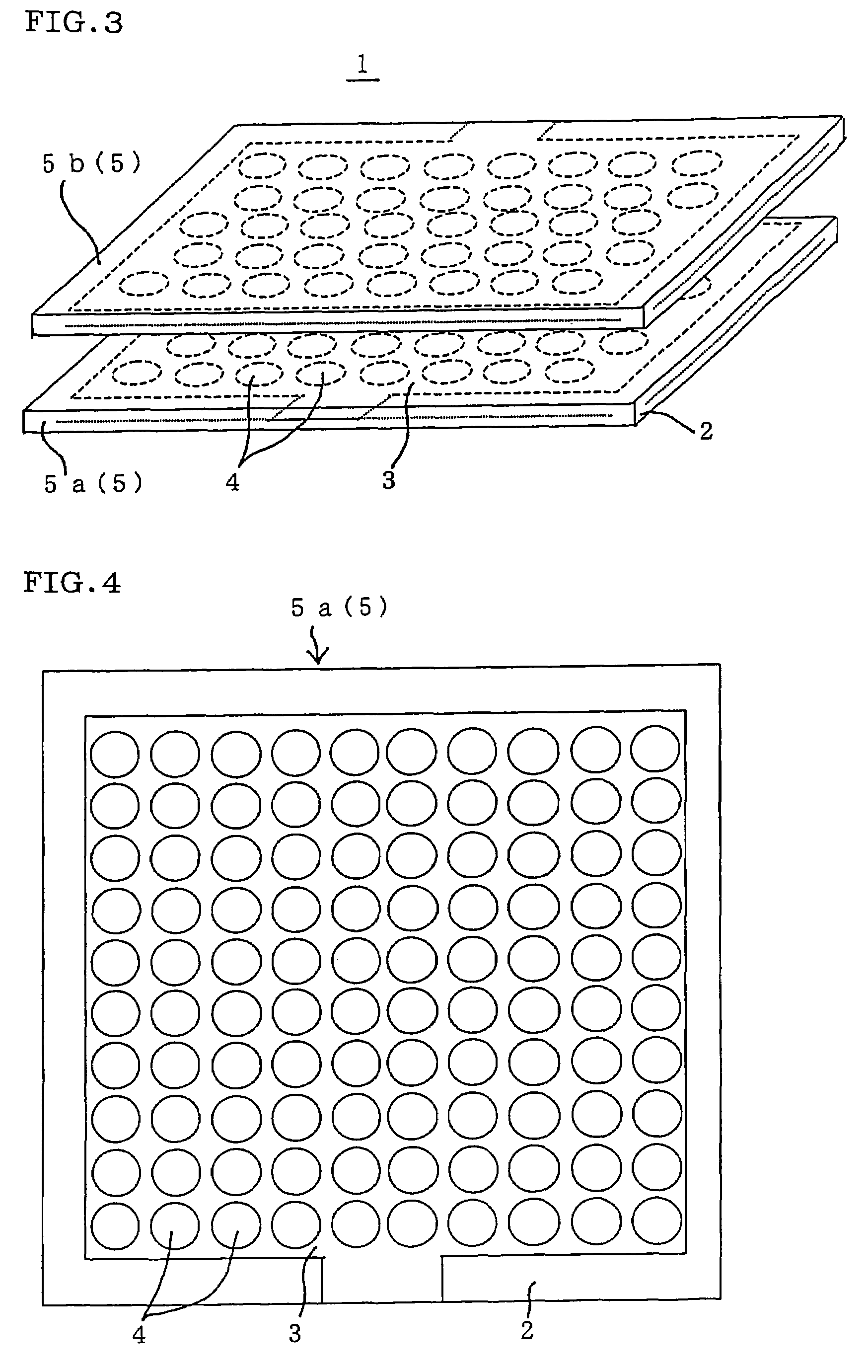
[0086]A plasma generation device was manufactured in the same manner as the plasma generation device of Example 1 except for disposing circular through-holes having a diameter of 5 mm at a center-to-center distance of 6 mm.

[0087]When causing a mixed gas similar to that described above to pass through the plasma generation device of the present example (Example 2), the NO concentration was reduced to 3 ppm at a power consumption of 18 W. This plasma generation device could convert NO at low power consumption in comparison with the plasma generation device of Example 1 so that high energy efficiency was obtained. This indicates that the diameter and the center-to-center distance of the through-holes affect power required to generate plasma.

example 3

[0088]A plasma generation device was manufactured in the same manner as the plasma generation device of Example 1 except for using a stainless steel electrode as one of the pair of electrodes constituting the plasma generating electrode.

[0089]The same mixed gas was caused to pass through the plasma generation device of the present example (Example 3). Electrification was performed at a voltage of 6 kV and a frequency of 500 Hz, and a mixed gas having an NO concentration of 200 ppm was caused to pass through plasma generated. As a result, the NO concentration was reduced to 5 ppm. At this time, the amount of power supplied to the plasma generation device was 40 W, so that power consumption was higher than that of Example 1. However, NO could be converted with high efficiency.


PUM

PropertyMeasurementUnit
diameteraaaaaaaaaa
center-to-center distanceaaaaaaaaaa
diameteraaaaaaaaaa

Abstract

A plasma generating electrode of the invention present includes at least a pair of electrodes 5, at least one electrode 5a of the pair of electrodes 5 including a plate-like ceramic body 2 as a dielectric and a conductive film 3 disposed inside the ceramic plate 2 and having a plurality of through-holes 4 formed through the conductive film 3 in its thickness direction, the through-holes having a cross-sectional shape including an arc shape along a plane perpendicular to the thickness direction. The plasma generating electrode can generate uniform and stable plasma at low power consumption.

Description

TECHNICAL FIELD[0001]The present invention relates to a plasma generating electrode, a plasma generation device, and an exhaust gas purifying device. More particularly, the invention relates to a plasma generating electrode and a plasma generation device capable of generating uniform and stable plasma at low power consumption. The invention also relates to an exhaust gas purifying device capable of purifying exhaust gas well.BACKGROUND ART[0002]It is known that silent discharge occurs when disposing a dielectric between two electrodes and applying a high alternating current voltage or a periodic pulsed voltage between the electrodes and that, in the resulting plasma field, active species, radicals, and ions are produced to promote reaction and decomposition of gas. This phenomenon may be utilized to remove toxic components contained in engine exhaust gas or incinerator exhaust gas.[0003]For example, a plasma exhaust gas treatment system has been disclosed in which NOx, carbon fine p...

Claims


Application Information

Patent Timeline
Patent Type & Authority Patents(United States)
IPC IPC(8): B23K10/00B01D53/56B01D53/74B01J19/08F01N3/08F01N13/02H05H1/24
CPCF01N3/0892H01J37/3244H01J37/32844F01N13/009H05H1/2406F01N2240/28H05H2001/2418H05H2245/121Y02C20/30H05H1/2418H05H2245/15
Inventor MIKI, MASANOBUDOSAKA, KENJIMIYAIRI, YUKIOFUJIOKA, YASUMASAMASUDA, MASAAKISAKUMA, TAKESHIHATANO, TATSUHIKO
Owner NGK INSULATORS LTD
Why Eureka
Try Eureka