System and method for optically imaging objects on a detection device by a pinhole aperture

a detection device and optical imaging technology, applied in the field of optical imaging objects, can solve the problems of large constructional space, falsification or preventing the acquisition and evaluation of true information to be transferred, and imaging systems are unsuitable for many fields of application

Inactive Publication Date: 2009-12-22
ROCHE DIAGNOSTICS OPERATIONS INC
View PDF15 Cites 9 Cited by
  • Summary
  • Abstract
  • Description
  • Claims
  • Application Information

AI Technical Summary

Benefits of technology

[0019]Although the present invention is not limited to specific advantages or functionality, it is noted that the present invention provides systems and methods for imaging optical patterns and in particular codes which fulfil the aforementioned requirements for such imaging systems for use in portable test element analytical systems. The present invention further provides the following features and advantages:
[0020]provides a simple and cost-efficient system for optically imaging objects on a detection device in a compact design which has a system-inherent brightness distribution in the detection plane that is as uniform as possible;
[0025]In accordance with another embodiment, a method for optically imaging an object is provided comprising providing an object located in an object plane; providing a detection device located in a detection plane; providing an illumination device; providing an optical attenuation element arranged between the illumination device and the object plane; illuminating the object with the illumination device; and imaging the object onto the detection device by a pinhole aperture, wherein the optical attenuation element substantially compensates for system-inherent imaging defects caused by the pinhole aperture.

Problems solved by technology

This would considerably complicate, falsify or prevent the acquisition and evaluation of the true information to be transferred.
It is inherent to the system that such systems require a large constructional space since the light source, object to be imaged and detection device have to be arranged one behind the other and they are therefore only of limited suitability for use in portable systems.
Consequently, such imaging systems are unsuitable for many fields of application.
In particular, the known imaging systems are only of limited suitability for incorporation into small and portable systems and in particular into diagnostic test element analytical systems.
In particular, no simple imaging systems are known which achieve a very uniform system-inherent brightness distribution in the detection plane using simple and cost-efficient means.

Method used


Image

  • System and method for optically imaging objects on a detection device by a pinhole aperture
  • System and method for optically imaging objects on a detection device by a pinhole aperture
  • System and method for optically imaging objects on a detection device by a pinhole aperture

Examples


Embodiment Construction

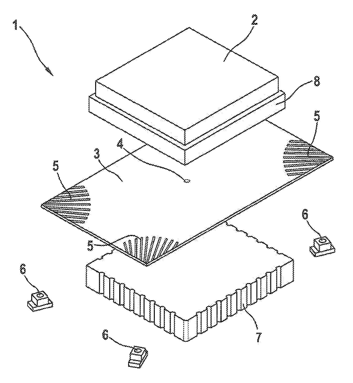
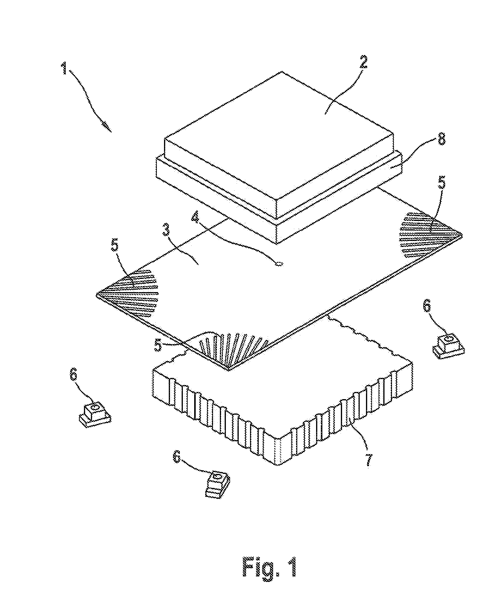
[0036]In accordance with the present invention, a system for optically imaging an object by a pinhole aperture is provided. Such an imaging system is based on the principle of the pinhole camera or camera obscura and has a pinhole aperture which is used to form an image of the object on the detection device. The principle of imaging by means of a pinhole aperture is for example explained in more detail in the “Lexikon der Optik” (Spektrum Akademischer Verlag, Heidelberg, Germany).

[0037]A major advantage of imaging systems based on the pinhole camera principle is that no lenses are required to form an image of the object. Lenses and systems of several lenses have construction-inherent imaging defects which considerably reduce the quality of the image and can thus make subsequent information processing impossible or erroneous. Construction-inherent imaging defects of optical lenses or lens systems are for example spherical aberration, chromatic aberration, color enlargement errors, co...


PUM


Abstract

Systems and method for optically imaging objects and in particular optical patterns or codes onto a detection device by a pinhole aperture are described. According to an embodiment of the invention these systems have optical attenuation elements between the illumination devices and the object which substantially compensate the system-inherent imaging detects caused by the pinhole aperture and in particular the system-inherent peripheral decrease in brightness of an image of the object formed by a pinhole aperture on the detection device. According to an embodiment of the invention, the optical attenuation elements change the illumination intensity of the object in such a manner that the central areas of the object are illuminated at a lower light intensity than its peripheral areas. As a result of the subsequent imaging of the object by a pinhole aperture, the central areas of the object are imaged onto the detection device at a higher light intensity than the peripheral areas of the object. The superimposition of the two effects enables the imaging system according to the invention to achieve a substantially uniform system-inherent brightness distribution on the detection device.

Description

BACKGROUND OF THE INVENTION[0001]The invention concerns systems for optically imaging objects, in particular information-carrying optical patterns of codes, on a detection device and in particular on a CCD or CMOS element with the aid of a pinhole aperture. The invention especially concerns systems that have devices which substantially compensate the imaging defects caused by the pinhole aperture and in particular the system-inherent peripheral decrease in brightness of an image of the object formed by a pinhole aperture on the detection device.[0002]In addition the invention concerns systems for capturing optical information which comprise such a system for optically imaging an object that carries optical information and an in-line evaluation device which collects the optical information of the object from the image of the object, formed on the detector device and provides this information for further processing or display.[0003]In addition, the invention concerns test element anal...

Claims


Application Information

Patent Timeline
Patent Type & Authority Patents(United States)
IPC IPC(8): H01L27/00G06V10/145
CPCG06K9/2036G06V10/145
Inventor AUGSTEIN, MANFREDDREIBHOLZ, JOERGFALK, DIETERKASS, UWEMACHO, HEINZ
Owner ROCHE DIAGNOSTICS OPERATIONS INC
Why Eureka
Try Eureka