Sanitary diaphragm valve

a diaphragm valve and sanitary technology, applied in the direction of diaphragm valves, engine diaphragms, machines/engines, etc., can solve the problems of significant capital expense, complex and difficult to repair and maintain sanitary valves used in dairy industry and other food processing industries, and achieve the effect of simple construction

Inactive Publication Date: 2009-12-29
FELDMEIER ROBERT H
View PDF12 Cites 11 Cited by
  • Summary
  • Abstract
  • Description
  • Claims
  • Application Information

AI Technical Summary

Benefits of technology

[0005]It is an object of the present invention to provide a sanitary diaphragm valve arrangement of simple construction, and capable of being cleaned in place when inst

Problems solved by technology

No threaded connectors can be used anywhere that the liquid product flows, because of the difficulty in cleaning the threads.
In order to accommodate this requirement, the sani

Method used


Image

  • Sanitary diaphragm valve
  • Sanitary diaphragm valve
  • Sanitary diaphragm valve

Examples


first embodiment

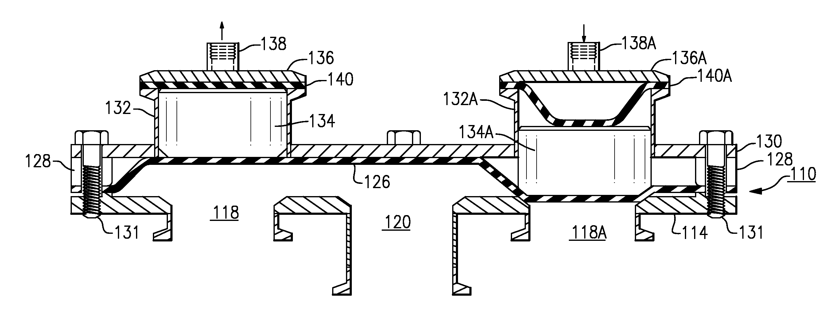
[0043]In this embodiment, the base or bottom plate 114 has a peripheral step 116, as in the first embodiment, and there is a diaphragm 126, spacer 128 and upper plate 130, as well as a series of bolts or other fasteners 31. The lower plate 114 has a first port 118 at the left, a central second port 120, and a third port 118A at the right. The upper plate has a pair of cylinders 132 and 132A situated to correspond to the positions of the first and third valve ports 118 and 118A, respectively. Each cylinder has a respective piston 134, 134A, an upper diaphragm 140, 140A held down by the respective cylinder cap 136, 136A, and each has an air inlet nipple 138, 138A. These air nipples are connected to respective control air lines (not shown).

[0044]FIG. 7 shows this diaphragm valve 110 with the left or first valve port 118 open, and with the third valve port 118A closed. That is, air pressure is relieved from the first cylinder 132 and air pressure is applied to the second cylinder 132A, ...

third embodiment

[0046]the diaphragm valve of this invention is shown in FIG. 8, in which the elements described in respect to the earlier embodiments are identified with similar reference numbers, but raised by “200”, and for which a detailed description can be omitted.

second embodiment

[0047]This valve 210 is similar to the diaphragm valve of the second embodiment, except that this valve 210 employs a pair of domed cylinders 232 and 232A situated in the upper plate 230. Here, the upper diaphragm members of the earlier embodiments are omitted from the cylinders. The pistons 234 and 234A are of a hollow cup shape to relieve weight and material, and there are seal rings present in the walls of the pistons, between the pistons and the inside walls of the cylinders 232 and 232A. The action and response of this valve 210 are similar to those of the valve 110.

[0048]Another embodiment, in which the valve is normally biased closed, and in which air is applied to open the valve, can be described with reference to FIG. 9. Here the relevant portions of a sanitary diaphragm valve 310 is shown, where the major elements of the valve are the same as described earlier, and similar parts are identified with similar reference numbers but raised by “300.” The cylinder 332 here has an...


PUM


Abstract

A sanitary diaphragm valve has a valve body formed of an upper plate and a lower plate, with a flexible resilient diaphragm and a spacer between them. The margin of the diaphragm rests on a peripheral step formed in the lower plate to create a positive space between the lower plate and the edges of the diaphragm. A piston within a cylinder in the upper plate can descend to compress the diaphragm against a valve port to close the valve. The pressure of the liquid product can raise the diaphragm and the piston when control pressure is relieved from the piston.

Description

BACKGROUND OF THE INVENTION[0001]This invention relates to equipment for processing of liquids used in products for human consumption, e.g., dairy products such as milk, cream, and ice cream mix, other liquid food products, e.g., fruit juices and soups, or pharmaceuticals. The invention is more particularly concerned with sanitary valves of the type used in the dairy, food processing, and / or pharmaceutical industries, in which the flow of a fluid is to be regulated or diverted from one flow path to another. The invention is also concerned with diaphragm valves, that is, valves of the type in which a flexible membrane conforms to a fluid port, when pressed against the port, to limit, restrict, or block the flow of the fluid. The invention is more specifically concerned with a diaphragm valve of simple design and which can be cleaned and sterilized in place by the flow of a cleaning liquid through the valve. Sanitary diaphragm valves of this type can be used in a milk pasteurization l...

Claims


Application Information

Patent Timeline
IPC IPC(8): F16K11/20
CPCF16K11/20Y10T137/87877Y10T137/87893
Inventor FELDMEIER, ROBERT H.
Owner FELDMEIER ROBERT H
Why Eureka
Try Eureka