Active carbon coated filter element for preventing the leaking of hydrocarbons

a technology of active carbon coating and filter element, which is applied in the direction of filtration separation, auxillary pretreatment, separation process, etc., can solve the problems of increasing the stringent limit on pollutant emission, and the ingress of hydrocarbons present in the intake tube of an internal combustion engine into the environment, so as to achieve the effect of increasing stability

Inactive Publication Date: 2009-12-29
MANN HUMMEL GMBH
View PDF8 Cites 8 Cited by
  • Summary
  • Abstract
  • Description
  • Claims
  • Application Information

AI Technical Summary

Benefits of technology

[0010]An important advantage of the present invention is that the filter element has a medium which is disposed in a plastic supporting frame. This plastic supporting frame can be inserted and fixed in an opening at the clean air end, while the frame enveloping the medium has at least two sealing lips and these sealing lips lie on the wall of the opening.
[0011]Another important advantage of the invention is that the medium is irremovable and secured against manipulation on account of the plastic holder and a direct seal by the sealing lips between the medium and the wall of the opening.
[0012]According to an embodiment of the invention the medium can be inserted into the plastic holder. Holding straps arranged on the plastic holder provide that the medium reaches the intended position. The plastic holder itself is fixed in the opening, with vibration welding. On account of the flexibility of the sealing lips, vibration welding into a vibration apparatus is possible which leads only to a shifting of the sealing lips—but not to leakage.
[0013]To increase stability, especially in the case of very large-area active carbon coated filter elements, the plastic holder is, according to a further embodiment, provided with a supporting grid. The medium lies on this supporting grid. Even great differential pressures produced due to a high air throughput do not result in a change in the position of the medium.
[0014]According to an embodiment of the medium, the medium includes pleated nonwoven material which is doped with active carbon. A U-shaped holding profile is provided to position the sealing lips on the nonwoven material. It bears the sealing lip and is placed over the last fold of the filter medium.
[0015]Such a filter element is used chiefly in internal combustion engines in which any outgassing of hydrocarbons from the intake tract is to be effectively prevented. For this purpose the filter medium closes an air intake duct.

Problems solved by technology

Increasing atmospheric pollution in nearly all countries has led to increasingly stringent limitation on pollutant emission.
As a consequence of the above-described SULEV / ULEV problem, it is disadvantageous, however, that due to the lack of materials that are capable of binding hydrocarbons, the hydrocarbons present in the intake tube of an internal combustion engine can enter into the environment.

Method used


Image

  • Active carbon coated filter element for preventing the leaking of hydrocarbons
  • Active carbon coated filter element for preventing the leaking of hydrocarbons
  • Active carbon coated filter element for preventing the leaking of hydrocarbons

Examples


Embodiment Construction

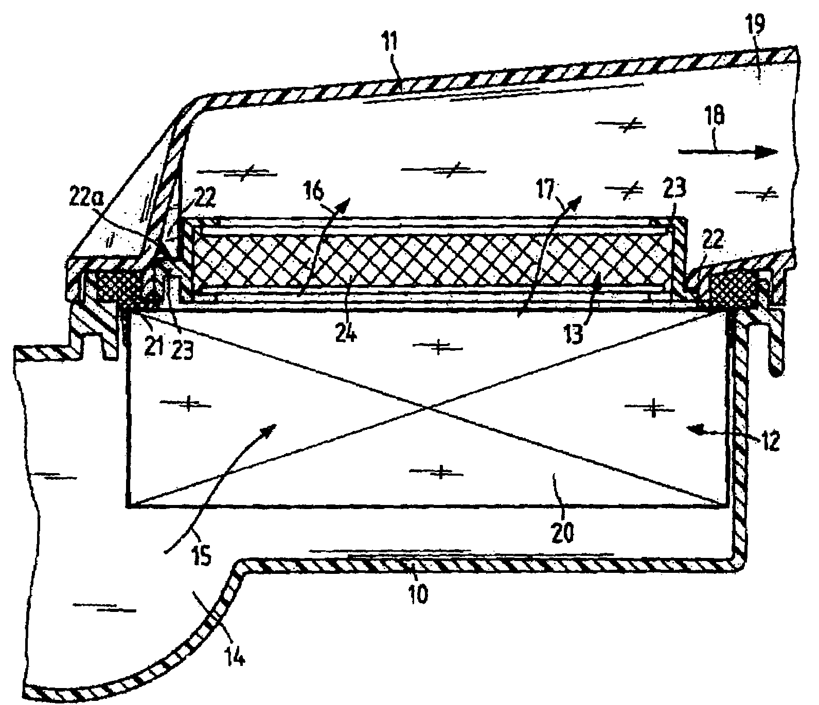
[0023]FIG. 1 shows an air intake filter system for an internal combustion engine, with a housing bottom 10, a housing top 11, a particle filter 12 arranged between the housing bottom 10 and the housing top 11, and an active carbon coated filter element 13 arranged above the particle filter. The intake air flows—beginning from the air intake opening 14—according to arrow 15 through the particle filter 12 and then according to arrows 16 and 17 through the filter element 13 into the clean air area, and is carried from there according to arrow 18 to the internal combustion engine not here shown. If the internal combustion engine is not in operation, fuel vapors enter into the clean air chamber 19, and without an active carbon coated filter element 13 they can pass through the particle filter 12 to the air intake opening 14 and thus into the environment. This, however, is effectively prevented by the filter element 13. The active carbon takes up hydrocarbons which might occur, and adsorb...


PUM

PropertyMeasurementUnit
shapeaaaaaaaaaa
blockage forceaaaaaaaaaa
flexibilityaaaaaaaaaa

Abstract

An active carbon coated filter element is proposed for preventing the issuance of hydrocarbons from an opening. It includes a medium containing active carbon, which is of substantially planar shape and has a frame. The frame is provided with sealing lips on at least two sides. The medium is arranged with the frame in a plastic holder, the plastic holder being able to be inserted and fixed in the opening. The sealing lips engage the wall of the opening.

Description

[0001]This application claims priority to German Application No. 10 2004 054 970.2, filed Nov. 13, 2004, the entire disclosure of which is incorporated herein by reference.FIELD OF THE INVENTION[0002]The present invention relates to an active carbon coated filter element and to such a filter element for an internal combustion engine.BACKGROUND OF THE INVENTION[0003]An important goal in the development of modern internal combustion engines is a reduction of pollutant emission. A purpose of development activities is an optimization of exhaust cleaning systems. Modern exhaust cleaning systems currently achieve pollutant conversion rates of over 97%.[0004]Increasing atmospheric pollution in nearly all countries has led to increasingly stringent limitation on pollutant emission. To assure repeatability and comparability, various testing methods, evaluations and limits have been considered. For example, in regard to limits in the USA, there is the category ULEV (Ultra Low Emission Vehicle...

Claims


Application Information

Patent Timeline
Patent Type & Authority Patents(United States)
IPC IPC(8): B01D50/00
CPCB01D46/0036B01D46/521B01D53/0415F02M35/024F02M35/04B01D46/10F02M2025/0863B01D2253/102B01D2253/25B01D2257/702B01D2258/012B01D2259/4516B01D2259/4566B01D2265/06B01D2271/02B01D2279/60
Inventor SCHOLL, HANS-PETERSCHOLZ, GUENTHERDAUBNER, HEINZRACKERSEDER, JOHANNLEBHERZ, REINHOLDPFEIFFER, FRANKSOHNEMANN, JENSSTAHL, JUERGENBRENNEIS, FRITZ
Owner MANN HUMMEL GMBH
Why Eureka
Try Eureka