D/A converter circuit

a converter circuit and converter technology, applied in the direction of digital-analog converters, transmission systems, instruments, etc., can solve the problem of taking a very large layout area, achieve the effect of reducing the layout area, preventing a bit inversion, and reducing the number of resistors

Active Publication Date: 2009-12-29
SEMICON COMPONENTS IND LLC
View PDF7 Cites 21 Cited by
  • Summary
  • Abstract
  • Description
  • Claims
  • Application Information

AI Technical Summary

Benefits of technology

[0010]With the resistor string type D / A converter circuit described above, reducing a layout area as well as preventing a bit inversion is made possible, because the number of resistors and the number of switches can be reduced.

Problems solved by technology

Although the bit inversion does not occur in the D / A conversion circuit using the resistor string, there is a problem that it takes a very large layout area (as large as five times of a layout area required by the R-2R type D / A converter circuit in the case of the nine-bit D / A converter circuit).

Method used


Image

  • D/A converter circuit
  • D/A converter circuit
  • D/A converter circuit

Examples


first embodiment

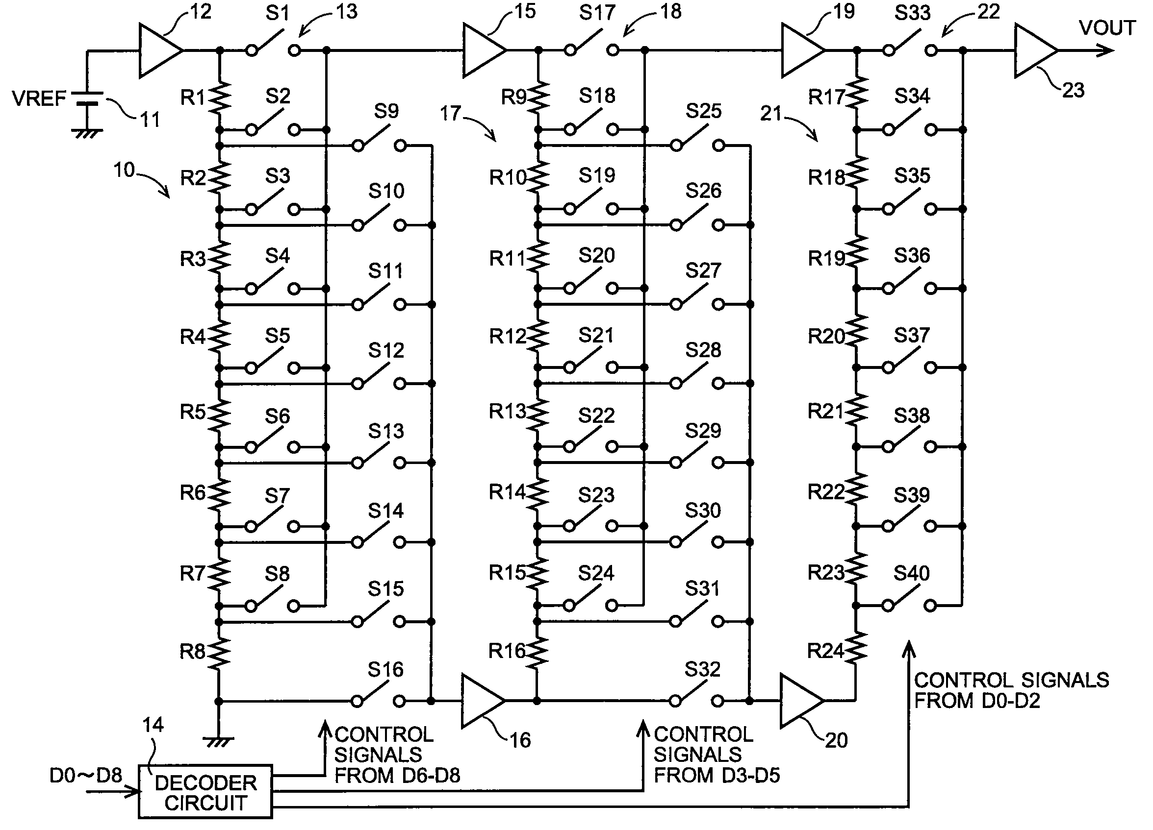
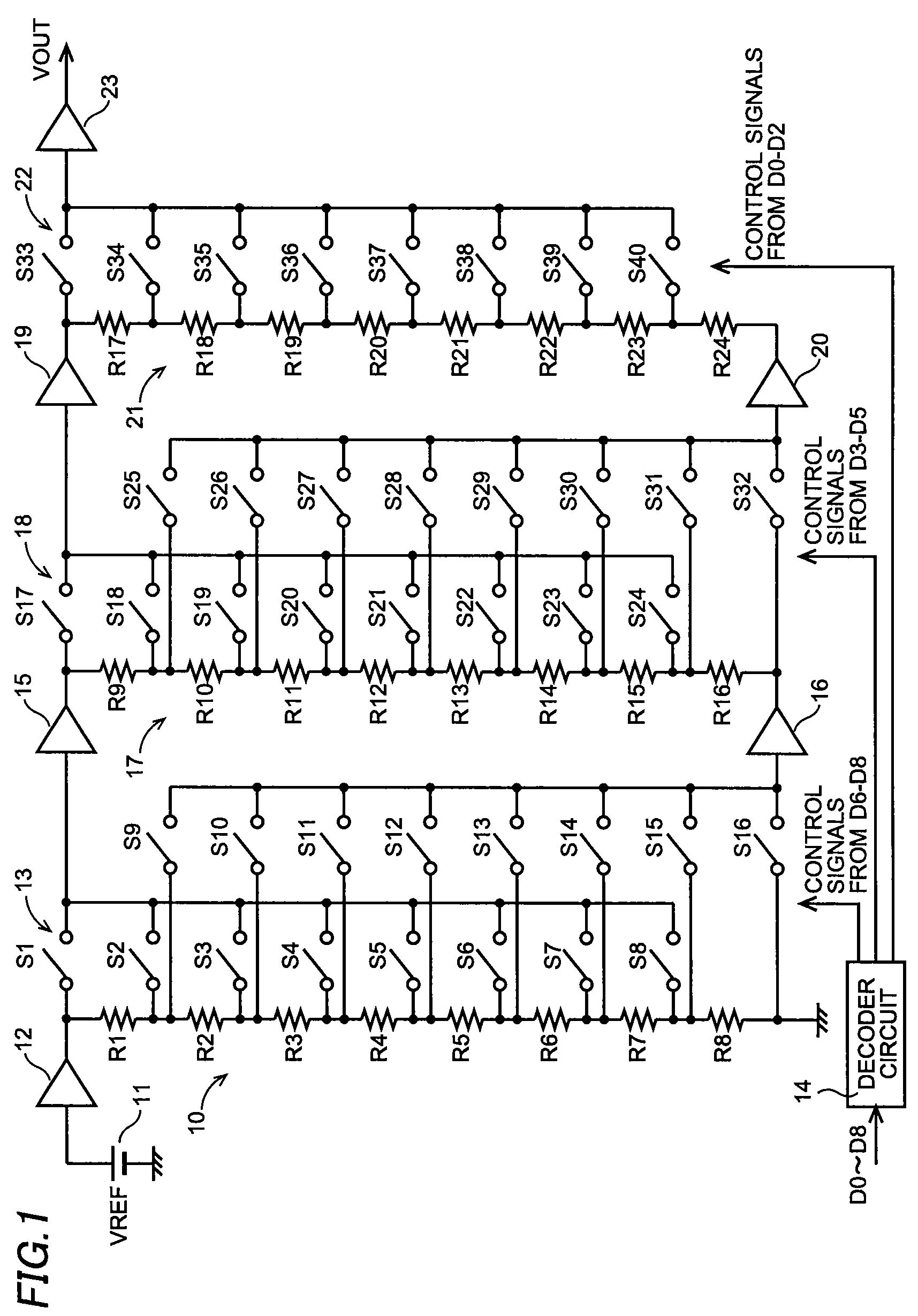
[0022]FIG. 1 shows a structure of a nine-bit D / A converter circuit according to this invention. A first resistor string 10 is composed of eight resistors R1-R8 connected in series. A reference voltage VREF generated by a reference voltage source 11 is supplied to an end of the resistor R1 through a buffer 12. An end of the resistor R8 is grounded. As a result, there are generated nine analog voltages ranging from 0 to VREF, each at each end of the resistors R1-R8 in the first resistor string 10. It is preferable that the resistors R1-R8 have the same resistance as the others so that the nine analog voltages increase by a constant increment.

[0023]A first switching circuit 13 is provided in order to select a pair of analog voltages generated across one of the resistors R1-R8 in the first resistor string 10. The first switching circuit 13 is composed of 16 switches S1-S16. A decoder circuit 14 decodes values of upper three bits (D8, D7, D6) in a nine-bit input digital signal D0-D8 to g...

third embodiment

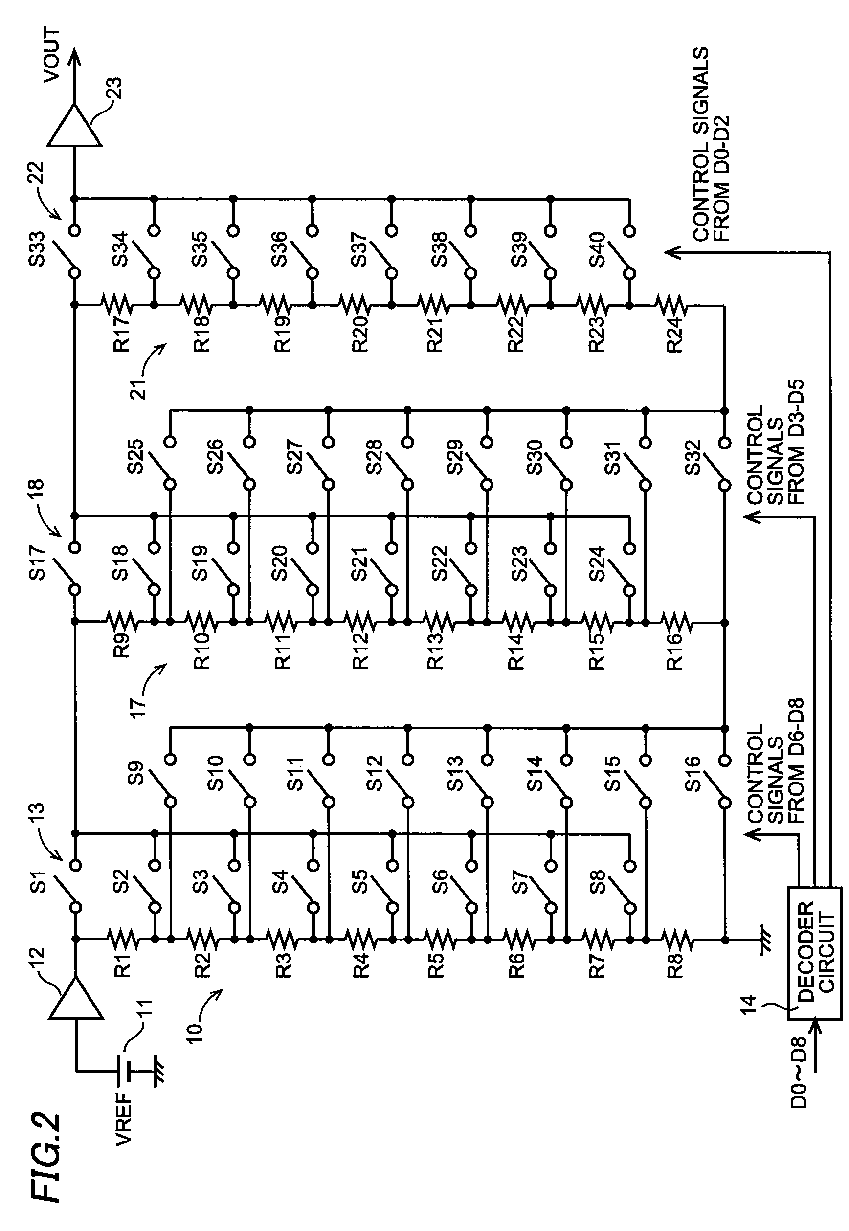
[0048]Considering the above, a D / A converter circuit according to this invention is provided with an adjusting resistor RH to adjust the abrupt change, which is connected in series with the resistors R9-R16 in the second resistor string 17, as shown in FIG. 5.

[0049]In addition, a resistor R25 is added to the first resistor string 10. Also, the first switching circuit 13 is modified so as to select a pair of analog voltages generated at both ends of two serially-connected neighboring resistors selected from among the resistors R1-R8 and R25. Table 4 shows correlation between the values of the upper three bits (D8, D7, D6) and the switches turned on accordingly.

[0050]

TABLE 4Switches TurnedD8D7D6ONVoltages Selected000S8, S16Voltages at Both Ends of R8-R25001S7, S15Voltages at Both Ends of R7-R8010S6, S15Voltages at Both Ends of R6-R7011S5, S13Voltages at Both Ends of R5-R6100S4, S12Voltages at Both Ends of R4-R5101S3, S11Voltages at Both Ends of R3-R4110S2, S10Voltages at Both Ends of ...


PUM


Abstract

A multi-bit D / A converter circuit that prevents a bit inversion and requires a reduced layout area is offered. A first switching circuit is provided in order to select a pair of analog voltages generated across one of resistors in a first resistor string. The selected pair of analog voltages is provided as reference voltages to a second resistor string. A second switching circuit is provided in order to select a pair of analog voltages generated across one of the resistors in the second resistor string. The selected pair of analog voltages is provided as reference voltages to a third resistor string. A third switching circuit is provided in order to select one of analog voltages generated in the third resistor string.

Description

CROSS-REFERENCE OF THE INVENTION[0001]This application claims priority from Japanese Patent Application No. 2007-163609, the content of which is incorporated herein by reference in its entirety.BACKGROUND OF THE INVENTION[0002]1. Field of the Invention[0003]This invention relates to a D / A converter circuit using resistor strings.[0004]2. Description of the Related Art[0005]An R-2R type D / A converter circuit has been known as a D / A converter circuit using ladder resistors. This type of D / A converter circuit is provided with the R-2R ladder resistors to which a reference voltage VREF is supplied, (n+1) constant current sources each corresponding to each of (n+1) bits (ranging from LSB (Least Significant Bit) to MSB (Most Significant Bit)) in a digital signal, respectively, and (n+1) switches S0-Sn each corresponding to each of the (n+1) bits in the digital signal, respectively, as shown in FIG. 9, and is capable of converting the (n+1) bit digital signal into an analog signal by turni...

Claims


Application Information

Patent Timeline
Patent Type & Authority Patents(United States)
IPC IPC(8): H03M1/66
CPCH03M1/682H03M1/765H03M1/66H03M1/12
Inventor IIJIMA, TAKASHI
Owner SEMICON COMPONENTS IND LLC
Why Eureka
Try Eureka