Position measurement apparatus and method and pattern forming apparatus and writing method

a technology of position measurement and pattern forming, applied in the direction of photomechanical equipment, digital computer details, instruments, etc., can solve the problems of nonlinear error, vertical and horizontal wave interference, position offset or displacement still occur, etc., and achieve the effect of high-quality position measuremen

Active Publication Date: 2009-12-29
NUFLARE TECH INC
View PDF18 Cites 413 Cited by
  • Summary
  • Abstract
  • Description
  • Claims
  • Application Information

AI Technical Summary

Benefits of technology

[0010]It is therefore an object of this invention to avoid the problems and provide a technique for correcting nonlinear errors to thereby achieve highly accurate position measurements.

Problems solved by technology

An example of such errors is a nonlinear error that occurs due to undesired interference between vertical and horizontal wave components as mixed in laser light.
Such vertical and horizontal wave interference is occurred by reflection of a laser beam at a mirror in measurement optics.
This kind of nonlinear error lowers the accuracy of the pattern formation, which poses a problem as to the incapability of accurate stage position measurements, resulting in the pattern write beam being irradiated or “shot” at deviant positions out of the target position on a workpiece mounted on the stage.
Unfortunately, position offsets or displacements are still occurrable due to the filtering characteristics of such filter.
Especially in the case of a stage as driven to move at varying speeds, the position measurement data signal experiences mixture of various nonlinear error components in addition to velocity-dependent nonlinear errors, such as acceleration-dependent nonlinear error components, variable acceleration errors, or other errors of higher order.
This causes unacceptable displacement or “miss shot” of the pattern write beam on the workpiece surface.

Method used


Image

  • Position measurement apparatus and method and pattern forming apparatus and writing method
  • Position measurement apparatus and method and pattern forming apparatus and writing method
  • Position measurement apparatus and method and pattern forming apparatus and writing method

Examples


embodiment 1

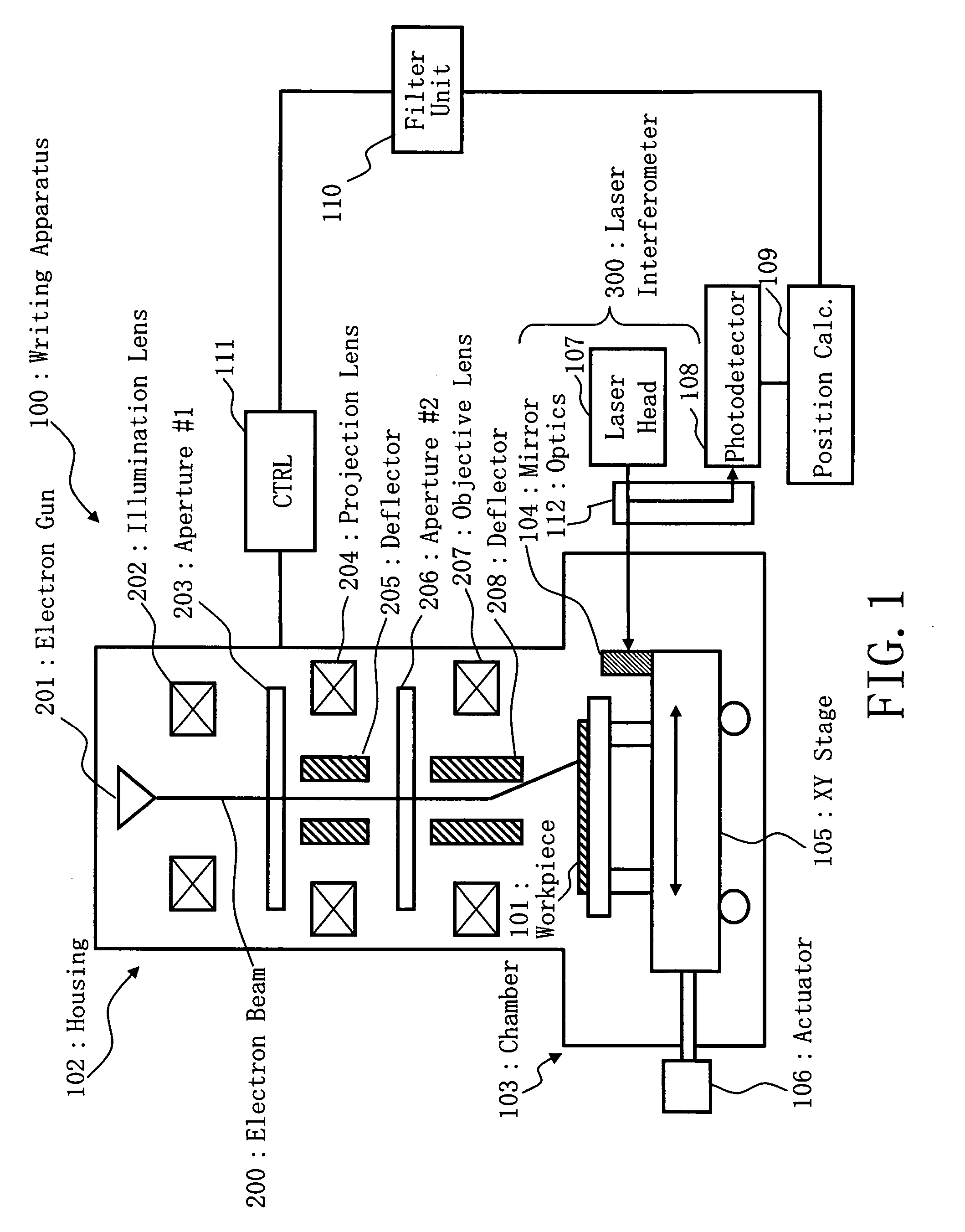
[0054]A variable-shaped electron beam (EB) writing apparatus 100 embodying the invention is shown in FIG. 1, which has an X-Y stage structure that is movable at a constant speed. As shown herein, the EB writing apparatus 100 includes a tower-like electron optics housing 102, called an electron lens barrel, a pattern writing chamber 103, a XY stage 105, and an actuator 106, as an example of writing or “drawing” unit. The writing apparatus 100 also includes a laser interferometer 300, as example of measurement unit, a position computing unit 109, a filter unit 110, and a pattern writing control circuit 111. Disposed in the barrel 102 are an electron gun assembly 201, illumination lens 202, upper or “first” aperture plate 203, projection lens 204, deflector 205, lower or “second” aperture plate 206, objective lens 207 and deflector 208. The laser interferometer 300 includes a light head 107, which may be a laser source for projecting a beam of laser light. Also included in the interfer...

embodiment 2

[0087]In Embodiment 2 XY stage 105 is driven to move at constantly increasing and decreasing speeds with fixed acceleration. A variable-shaped electron beam writing apparatus in accordance with embodiment 2 is similar to that shown in FIG. 1, expect an internal configuration of the filter unit 110. the EB writing apparatus 100 includes a tower-like electron optics housing 102, called an electron lens barrel, a pattern writing chamber 103, a XY stage 105, and an actuator 106, as an example of writing or “drawing” unit. The writing apparatus 100 also includes a laser interferometer 300, as example of measurement unit, a position computing unit 109, a filter unit 110a, and a pattern writing control circuit 111. Disposed in the barrel 102 are an electron gun assembly 201, illumination lens 202, upper or “first” aperture plate 203, projection lens 204, deflector 205, lower or “second” aperture plate 206, objective lens 207 and deflector 208. The laser interferometer 300 includes a light ...

embodiment 3

[0111]A variable-shaped electron beam lithography apparatus in accordance with a further embodiment of the invention is arranged to employ a stage position measurement technique which offers enhanced supportability to an XY stage that is driven to move while varying the acceleration as well as the XY stage moving with fixed acceleration as in the embodiment stated supra. A position measurement method capable of removing nonlinear error components occurring while the stage is in motion with varying acceleration will be described below. A variable-shaped electron beam writing apparatus in accordance with embodiment 3 is similar to that shown in FIG. 1, except an internal configuration of the filter unit 110.

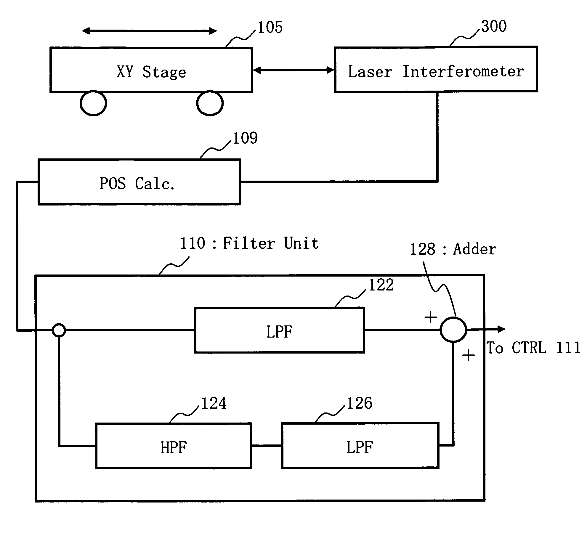
[0112]FIG. 26 shows an internal configuration of a filter unit 110 in accordance with an embodiment 3. Upon receipt of an output signal of the laser interferometer 300 which indicates a present position of the moving XY stage 105, the position calculator 109 converts it to a positi...


PUM


Abstract

A position measurement apparatus includes a movable stage structure, a measurement unit using a laser to measure a moved position of the stage and to output a corresponding measured value, a first filter configured to attenuate a first component of a certain frequency region of the measured value outputted by the measurement unit, a second filter connected in parallel with the first filter configured to attenuate a second component other than the certain frequency region of the measured value outputted by the measurement unit, a third filter connected in series to the second filter with the series connection of the second and third filters connected in parallel with the first filter, configured to attenuate the first component of the certain frequency region of the measured value outputted by the measurement unit, and a processing unit configured to combine an output of the first filter and an output of the series connection of the second and third filters and to thereby output a first combined value.

Description

CROSS-REFERENCE TO RELATED APPLICATIONS[0001]Priority is claimed to Japanese Patent Application No. JP 2005-218226 and to Japanese Patent Application No. JP 2005-218227, both filed Jul. 28, 2005, the disclosures of which are incorporated herein by reference.FIELD OF THE INVENTION[0002]The present invention relates generally to position measurement technologies and writing technologies and, more particularly, to a technique for optically measuring and detecting a present position of a moving stage structure.DESCRIPTION OF RELATED ART[0003]In recent years, highly integrated semiconductor devices require more and more decreased feature size in on-chip patterns with an increase in integration density of large-scale integrated (LSI) circuits. To form a desired circuit pattern on such semiconductor devices, a microlithographic exposure apparatus is used. A prior known approach to doing this is to employ a process having the steps of placing a chosen one of masks (e.g., reticles or photoma...

Claims


Application Information

Patent Timeline
Patent Type & Authority Patents(United States)
IPC IPC(8): H04B15/00
CPCB82Y10/00B82Y40/00H01J37/3174G03F9/7092H01J2237/31793G03F7/70725G03F7/70775G03F9/7065
Inventor TACHIKAWA, YUICHIYASUI, KAZUMICHINAKASO, KIYOSHIHATTORI, KIYOSHIOKUYA, TSUGIYUKIMITA, MAKOTO
Owner NUFLARE TECH INC
Why Eureka
Try Eureka