Fuel cell vehicle

a fuel cell and vehicle technology, applied in the direction of electric propulsion mounting, electric propulsion mounting, electrochemical generator, etc., can solve the problems the difficulty of simultaneously meeting both requirements, and the difficulty of lowering the height of the vehicle floor, etc., to achieve the effect of simple structur

Inactive Publication Date: 2010-01-05
HONDA MOTOR CO LTD
View PDF45 Cites 16 Cited by
  • Summary
  • Abstract
  • Description
  • Claims
  • Application Information

AI Technical Summary

Benefits of technology

[0009]An object of the present invention is to provide a fuel cell vehicle that can protect the fuel cell and related equipment from obstructions under the vehicle floor with a lightweight and simple structure.
[0010]Another object of the present invention is to provide a fuel cell vehicle provided with a subframe that ensures mechanical strength while being lightweight. Still another object of the present invention is to provide a fuel cell vehicle that allows for a lowering of the vehicle floor.

Problems solved by technology

Simultaneously meeting both requirements has thus proven to be difficult.
Disposing the fuel cell and related components under the vehicle floor has also given rise to the issue of lowering the height of the vehicle floor.
This has therefore posed a hurdle to lowering the height of the floor.

Method used


Image

  • Fuel cell vehicle
  • Fuel cell vehicle
  • Fuel cell vehicle

Examples


Embodiment Construction

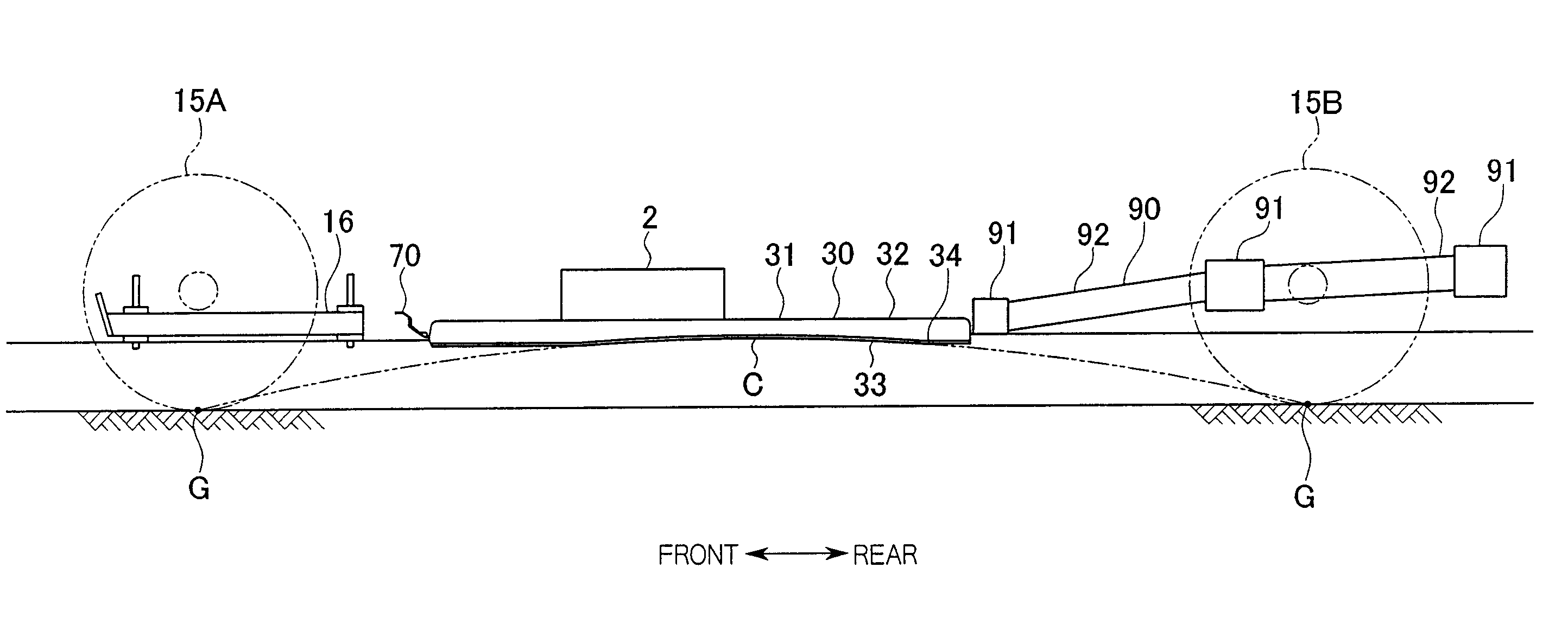
[0041]An embodiment of the fuel cell vehicle according to the present invention shall be explained hereinbelow with reference to FIGS. 1 to 14. In the drawings, the arrows pointing in the front, rear, left, and right directions refer to the front, rear, left, and right of the vehicle body, respectively.

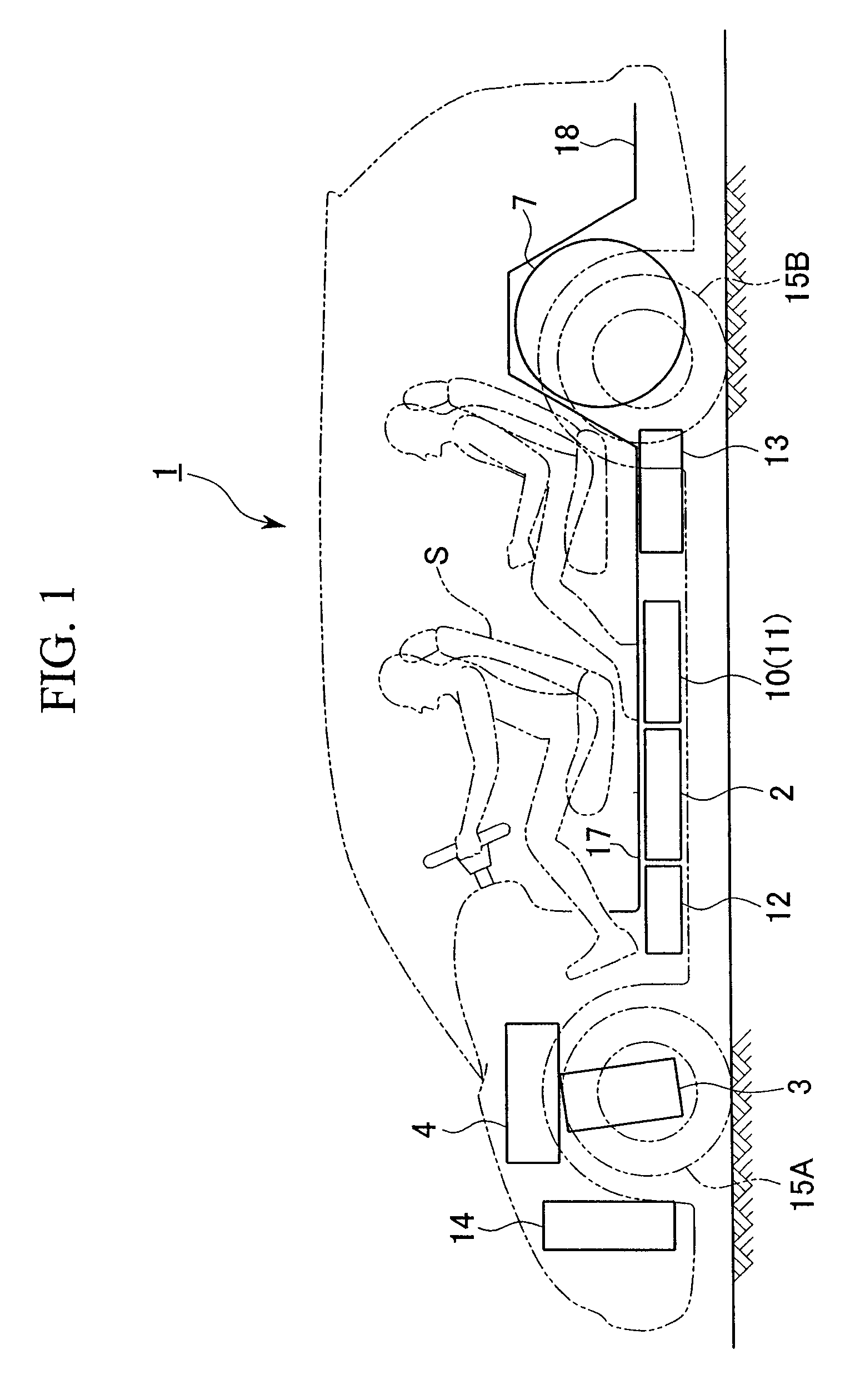
[0042]As shown in FIG. 1, a fuel cell vehicle 1 is one equipped with a fuel cell 2 that generates electricity by the electrochemical reaction of hydrogen and oxygen, and travels by driving a drive motor 3 with electric power produced by this generation

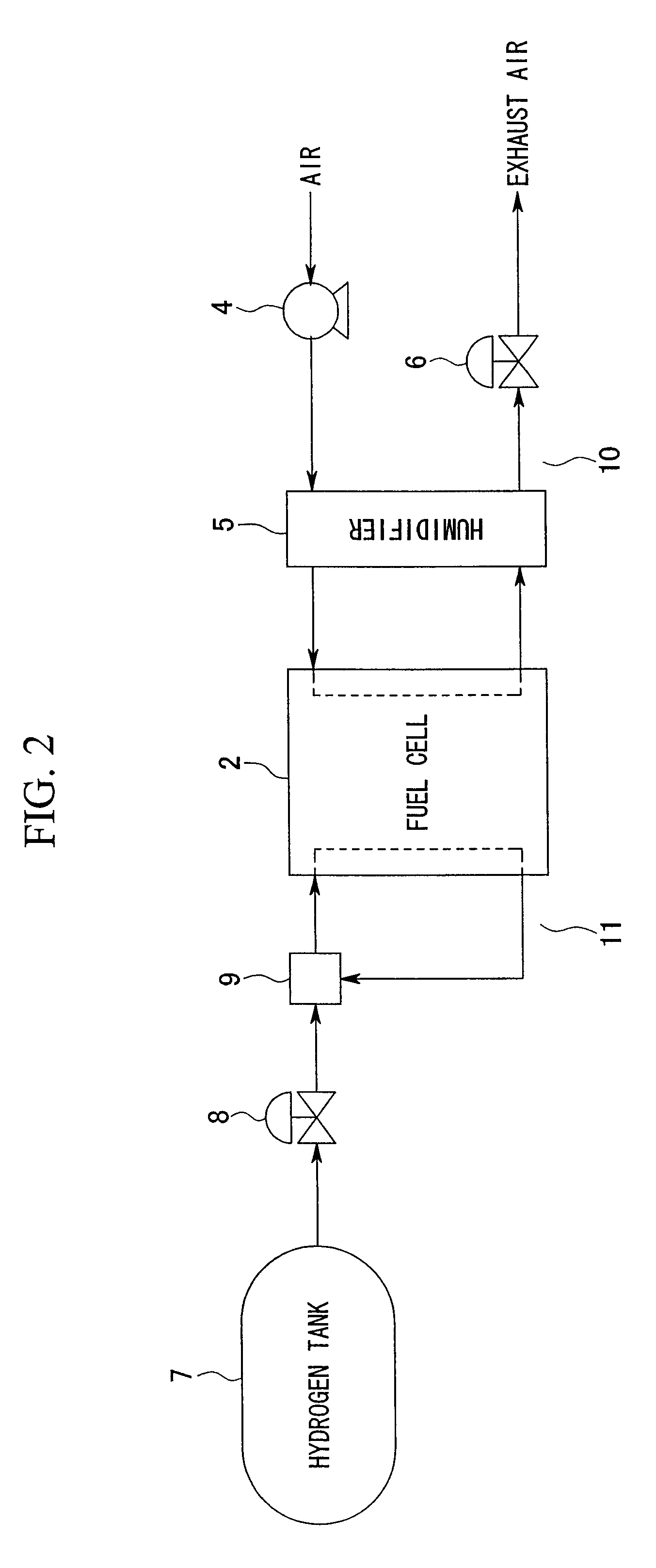
[0043]FIG. 2 shows an outline of the fuel cell system. As shown in FIG. 2, air including oxygen that is compressed by a compressor 4 is humidified with a humidifier 5 and then supplied to the cathode of the fuel cell 2. After electricity generation, it is discharged from the fuel cell 2 and, after circulating through the humidifier 5 as a humidity source, is discharged through a pressure control valve 6. On the other side, hydrogen gas f...


PUM


Abstract

A fuel cell vehicle includes a vehicle body having a floor frame; a fuel cell that generates electricity by the electrochemical reaction of hydrogen and oxygen; and a subframe on which the fuel cell is mounted, being attached to the lower side of the floor frame and has a pair of side frames that extend in the fore-aft direction of the vehicle body, wherein the bottom end of the fuel cell disposed at a position between the upper end and the lower end of the subframe.

Description

BACKGROUND OF THE INVENTION[0001]1. Field of the Invention[0002]The present invention relates to a fuel cell vehicle equipped with an electric motor powered by a fuel cell.[0003]Priority is claimed on Japanese Patent Applications No. 2005-162393, No. 2005-162395, and No. 2005-162396 filed Jun. 2, 2005, the content of which is incorporated herein by reference.[0004]2. Description of Related Art[0005]There is known a fuel cell mounting structure for a fuel cell vehicle that provides a subframe on which are mounted the fuel cell and auxiliary components thereof, with the subframe being fastened to vehicle body frame members from below to be disposed under the vehicle floor. (see, for example, Japanese Unexamined Patent Application, First Publication No. 2003-182624.)[0006]When mounting a fuel cell and the like on such a subframe to be disposed under the vehicle floor, care must be taken so that obstructions on the road do not interfere with the fuel cell.[0007]Mechanical strength is re...

Claims


Application Information

Patent Timeline
Patent Type & Authority Patents(United States)
IPC IPC(8): B60K1/04
CPCB60K1/04B60K15/063B62D25/20H01M8/2475B60K15/07B60K11/04B60K13/02Y02T90/32B60K2015/0638H01M2250/20Y02E60/50Y02T90/40
Inventor NOZAKI, SHUJIROKATO, TAKASHIANAZAWA, MAKOTONAKAARAI, MASATO
Owner HONDA MOTOR CO LTD
Why Eureka
Try Eureka