

Cross-flow fan propulsion system
a technology of cross-flow fan and propulsion system, which is applied in the direction of air-flow influencers, vertical landing/take-off aircraft, aircraft navigation control, etc., can solve the problems of inconvenient use, inconvenient use, and inconvenient use of the cff housing, so as to reduce the flow separation and low parasite drag
- Summary
- Abstract
- Description
- Claims
- Application Information
AI Technical Summary
Benefits of technology
Problems solved by technology
Method used
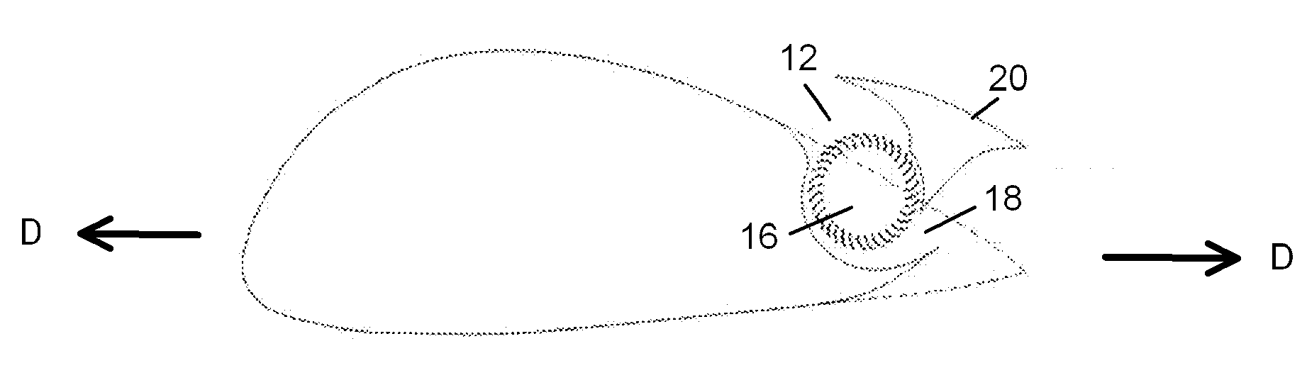
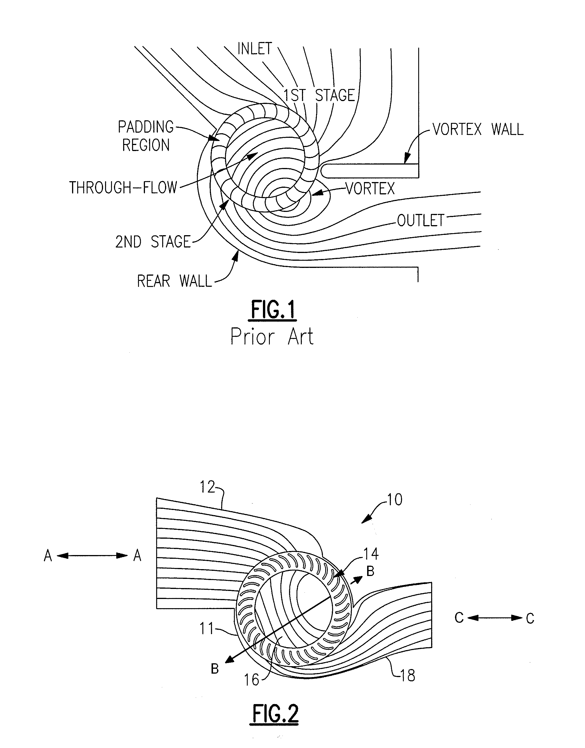
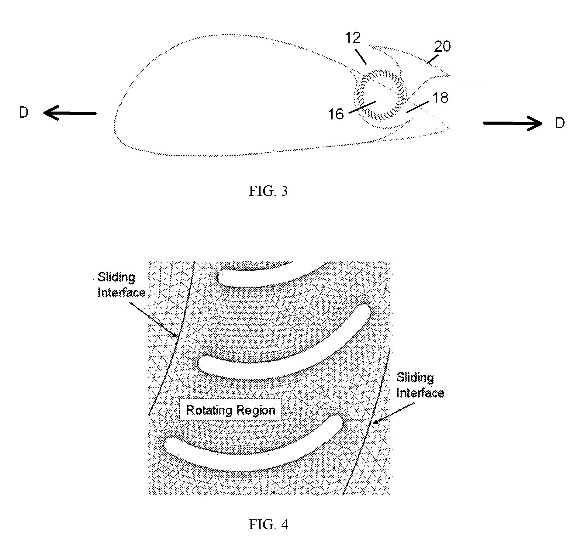
Image

Examples
Embodiment Construction
[0040]Glossary:
[0041]A=area
[0042]CD=airfoil drag coefficient, D / (0.5 ρU∞2C)
[0043]CL=airfoil lift coefficient, L / (0.5 ρU∞2C)
[0044]CP=power coefficient, Power / (ρU∞3Df)
[0045]CT=thrust coefficient, T / (0.5 ρU∞2Df)
[0046]CS=control surface
[0047]D=drag per unit span
[0048]DBL=drag due to boundary layer build-up
[0049]Df=cross-flow fan diameter
[0050]Fx=x-component of force
[0051]H=arbitrarily large distance
[0052]hi=propulsor inlet height
[0053]hj=propulsor outlet height
[0054]hw=ingested wake height
[0055]{tilde over (h)}=non-dimensionalized ingested wake height
[0056]L=lift per unit span
[0057]{dot over (m)}=mass flow rate
[0058]p=variable
[0059]PP=propulsive power
[0060]PT=total pressure
[0061]PTi=total pressure at propulsor inlet
[0062]PTi=mass-weighted total pressure at propulsor inlet
[0063]Q=flow rate per unit span
[0064]r=radial distance
[0065]T=propulsor thrust
[0066]U=velocity
[0067]Uf=fan tip speed
[0068]Ũj=non-dimensionalized jet velocity, Uj / U∞
[0069]UW =propulsor inlet velocity with wake ingestion
[...
PUM
 Abstract
Description
Claims
Application Information