Information system and method for providing information using a holographic element

a technology which is applied in the field of information system and holographic element providing information, can solve the problems of cumbersome shape, difficult to implement such a system or method so cost-effectively, and disadvantage of cumbersome shap

Active Publication Date: 2010-01-05
APPLE INC
View PDF23 Cites 163 Cited by
  • Summary
  • Abstract
  • Description
  • Claims
  • Application Information

AI Technical Summary

Benefits of technology

[0045]As described above, a holographic element influences only the light incident on it which meets the above-mentioned holographic criteria. It is currently difficult to produce holograms which influence light over a wide spectral range. The invention therefore preferably provides that the holographic element refracts light originating from the field of vision of the eye only at several discrete wavelengths in the visible spectral range. Such a hologram can be produced at low expenditures, for example, by an illumination which is correspondingly repeated at the relevant wavelengths. The effects of the light detection limited as a result of the restricted spectral transmissivity of the light-guiding hologram can be compensated or reduced by the corresponding adaptation of the information system to the detectable wavelengths. For example, among other things, by the corresponding processing of the signals obtained from the detected light in the information system, analogous to the principle of a flat-bed scanner which detects only filtered red, green and blue light, a highly valuable color picture of the environment could be obtained. Since analogously a hologram normally represents a very narrow-band filter, it may be meaningful for the holographic element to refract light at more than the conventional three (red, green, blue) wavelengths in the direction of the scanning device in order to be able to obtain, for example, from the detected light, a picture which is as true-to-nature as possible. If, however, too many holographic recordings are captured in a single hologram, this results in a mutual impairment of their effect.
[0270]Nevertheless, a common beam path ensures that projected light beams, which are beamed back against the projection direction, for example, from the eye, are, as it were, “automatically” guided to the scanning device. As a result, a high-expenditure “synchronization” of a light guiding device assigned to the scanning device and of a light guiding device assigned to the projection device can be eliminated.

Problems solved by technology

However, it is difficult to implement such a system or method so cost-effectively that it is accessible to the general public.
However, here also, it is difficult to implement such a device or method so cost-effectively that it is accessible to the general public.
This system, however, has the disadvantage of having cumbersome shape.

Method used


Image

  • Information system and method for providing information using a holographic element
  • Information system and method for providing information using a holographic element
  • Information system and method for providing information using a holographic element

Examples


first embodiment

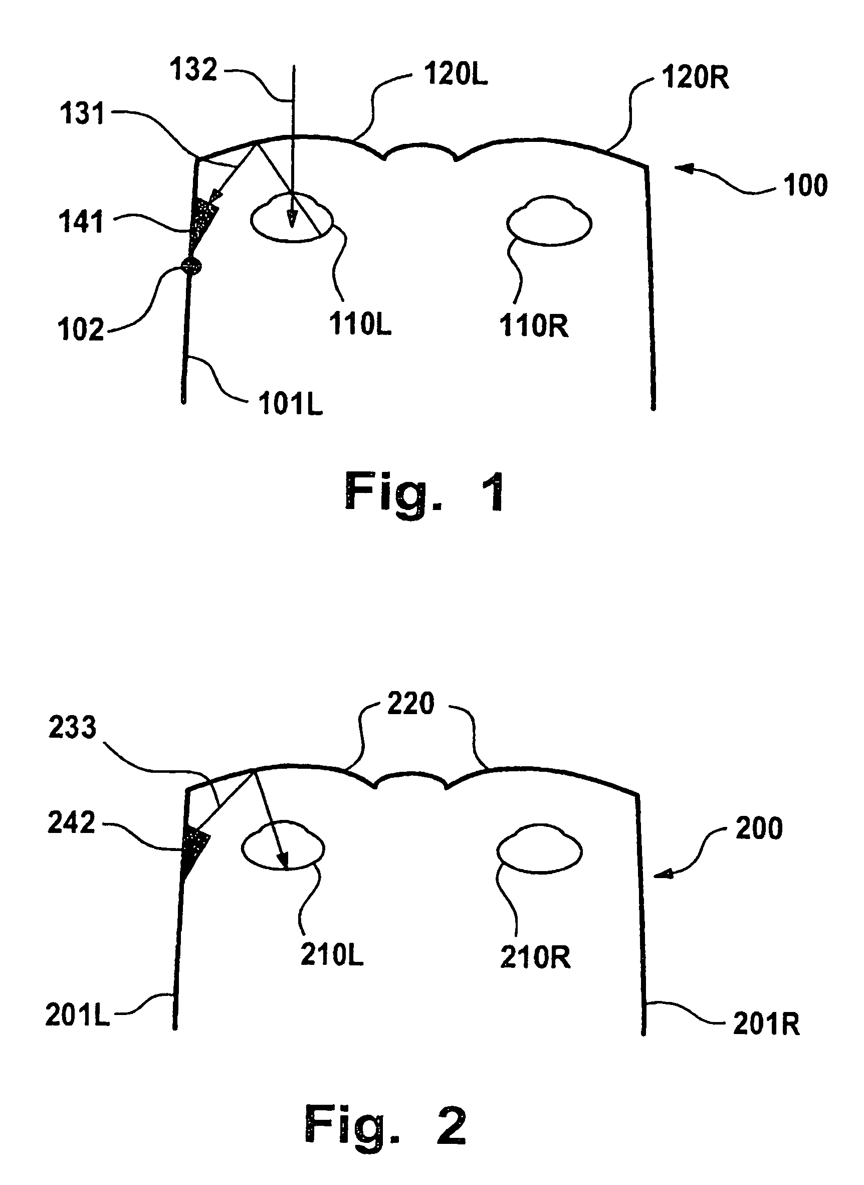
[0300]FIG. 1 is a schematic representation of a scanning information system 100 according to the invention, in which the scanning information system 100 is designed in the shape of spectacles 100 that have two holographic elements 120R, 120L in the form of spectacle lenses 120R, 120L arranged in front of each 110R, 110L. On the left bow 101L of the spectacles 100, a scanning device 141 is fastened which is capable of detecting light beams 131 coming from the eye 110. The scanning device 141 preferably comprises a light guiding device (not shown) such as a scanner device, which determines the momentary detection direction of the scanning device 141 and changes time, according to a predetermined scan pattern. Naturally, an additional scanning device (not shown) could also be fastened on the right bow 101R. The light beam 132 indicates that light beams 132 originating from the environment are allowed to pass unhindered by the holographic element 120.

[0301]In this embodiment, the hologr...

second embodiment

[0303]FIG. 2 is a schematic representation of a projecting information system 200 in which the projecting information system 200 is designed in the form of spectacles 200 having two holographic elements 220 constructed as spectacle lenses 220 each arranged in front of an eye 210. On the left bow 201 L of the spectacles 200, a projection device 242 is fastened which is capable of projecting light beams 233 onto or into the eye 210. The projection device 242 preferably comprises a light guiding device(not shown), for example, a scanner device which determines the momentary projecting direction of the projection device 242 and changes it with respect to time according to a predetermined projection pattern. Naturally, an additional projection device, which is not shown, could also be fastened on the right bow 201R.

[0304]In this embodiment, the holographic element 220 is used only for refracting light beams 233 projected by the projection device 242 in the direction of the eye 210. The ...

third embodiment

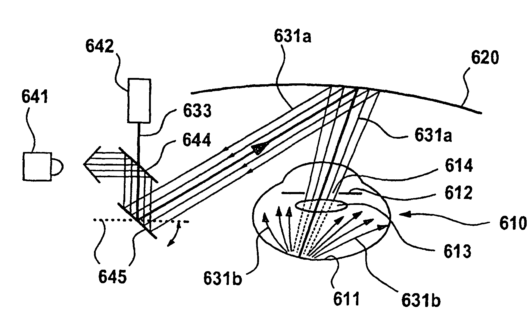
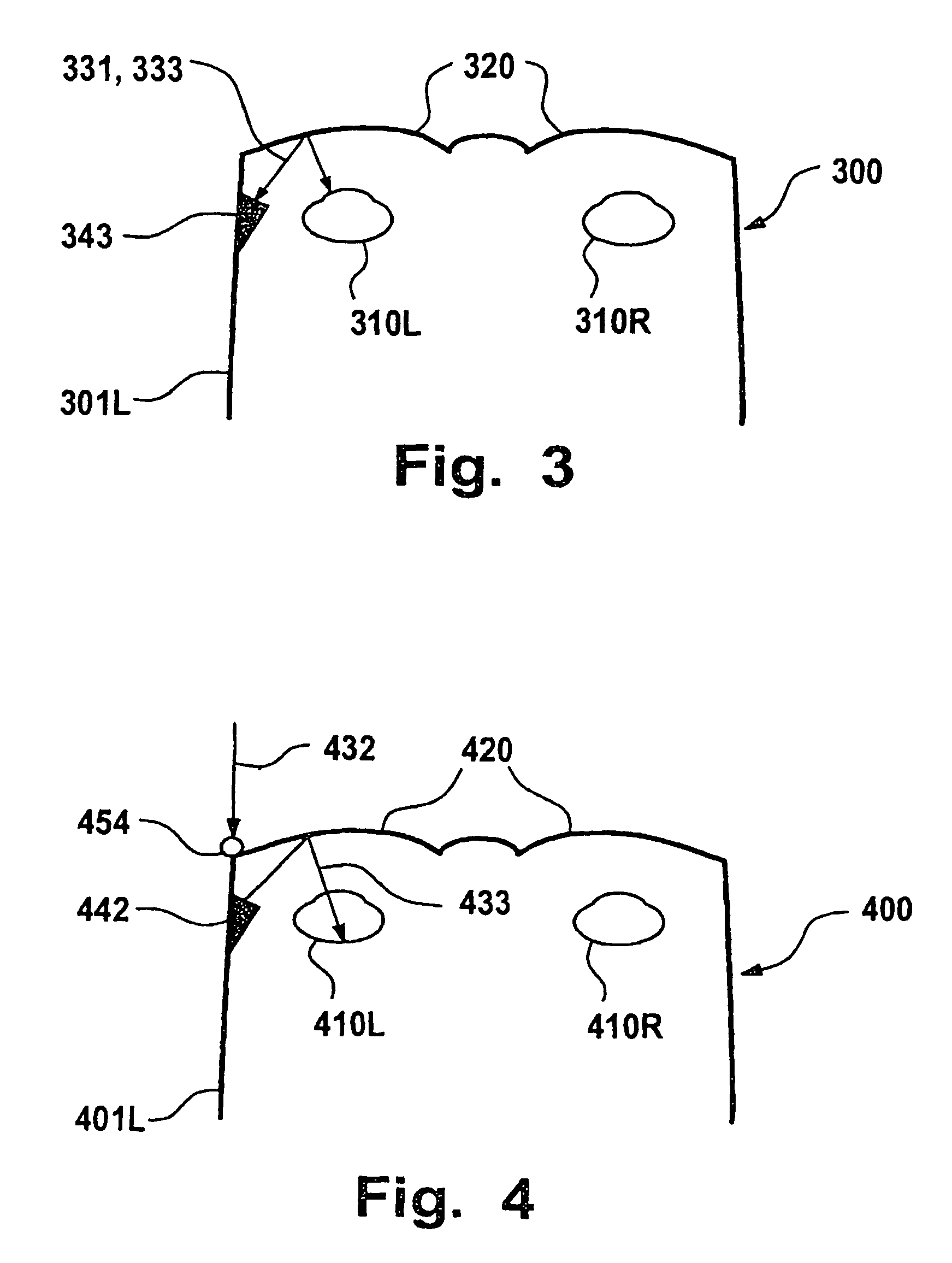
[0305]FIG. 3 is a schematic representation of an information system 300 in which the information system 300 is designed in the form of spectacles 300, with two holographic elements 320 designed as spectacle lenses 320 which are each arranged in front of an eye 310. At the left bow 201L of the spectacles 200, a combined projection and scanning device 343 is fastened, which is capable of projecting light beams 333 onto or into the eye 320 as well as also detecting light beams 331 coming from the eye 310. The projection device 343 preferably comprises a light guiding device (not shown), such as a scanner device, which projects the momentary projecting direction of the projection device 343 and changes it with respect to time according to a predetermined projection pattern.

[0306]Such an information system 300 could be used, for example, for illuminating the retina of the eye 310 in an actively point-focal manner, and to detect the light 331 reflected in by the retina for the purpose of...


PUM


Abstract

In an information system and a method for providing information in correlation with light that is incident on an eye, a pair of spectacles includes a holographic element that is supported in front of the eye of a wearer of the spectacles. An optical scanning device detects light that is incident on the eye via the holographic element.

Description

BACKGROUND OF THE INVENTION[0001]The present invention relates to an information system and as well as to a method for providing information using a holographic element, particularly in correlation with a light that is incident on an eye.STATE OF THE ART[0002]In the European Patent Documents PCT / EP00 / 09843, PCT / EP00 / 09840, PCT / EP00 / 09841, PCT / EP00 / 09842, which were all filed on Oct. 7, 2000, and German Patent Application DE 101 27 826, which was filed on Jun. 8, 2001, multiple information, projection and recording systems as well as corresponding methods are described which have the object of providing information in a manner adapted to the demands of a seeing person. However, it is difficult to implement such a system or method so cost-effectively that it is accessible to the general public.[0003]In European Patent Document PCT / EP01 / 05886, multiple methods and devices for adapting an optical system to the viewing direction of the human eye, and pertaining systems for determining th...

Claims


Application Information

Patent Timeline
Patent Type & Authority Patents(United States)
IPC IPC(8): A61B3/10G02B27/14G02C5/00A61B3/113A61B3/12G02B27/01G06F3/00G06F3/01
CPCA61B3/113A61B3/12G02B27/017G06F3/013A61B3/14G02B5/32G02B27/0172G09G5/00G02B2027/0174G02B2027/0178G06F3/04815G02B2027/0138G02B27/0093
Inventor EBERL, RONALD H.EBERL, HEINRICH A.DICKERSON, DAVID
Owner APPLE INC
Why Eureka
Try Eureka