Electrostatic precipitator

a precipitator and electrostatic technology, applied in the field of electrostatic precipitators, can solve the problems of increasing the workload of employees, increasing the cost of exchange, and large bulky dry- and wet-type electrostatic precipitators, and achieve the effect of a distance equal to the absorption surfa

Inactive Publication Date: 2010-01-05
ZESU GIKO +1
View PDF15 Cites 9 Cited by
  • Summary
  • Abstract
  • Description
  • Claims
  • Application Information

AI Technical Summary

Benefits of technology

[0015]In particular, there is a demand for an electrostatic precipitator with a high operating rate that is capable of collecting dust at a steady rate without a marked reduction in its dust-collecting rate (dust-capturing efficacy) even when it is operated continually for a long time and with its adsorptive surface with particles in an adsorbed state can be cleansed relatively easily and in a short time so that it may be used again.
[0022]On the other hand, the adsorption plate has an electrical potential opposite that of the charged particles and it tends to adsorb these particles with the aid of the Coulomb force. Consequently, the particles that had been brought between the charging and absorption plates come under the repelling and absorptive effects, drawn to the absorption surface of the adsorption plate and collected. At this moment, the absorption plate is rotated by the plate rotating means that is connected to the adsorption shaft. Therefore, the positional relationship of the adsorption surface of the adsorption plate with the particles constantly changes, keeping the particles from accumulating in any specific site on the adsorption surface. In other words, the efficiency of adsorption and collection by the Coulomb force is not reduced by accumulated particles and the dust-collecting efficacy of the electrostatic precipitator is not compromised in a short period.
[0024]Thus, in the electrostatic precipitator of the present invention, the pointed ends of the discharge electrode are arranged away from the plate edge of the adsorption plate and toward the side of the adsorption shaft. Specifically, contaminated air, which has passed through the inlet, reaches between a pair of opposing adsorption plates and arrives at the charging plate where the discharge electrode is located. Because of the electrical field that has been formed by a supply of the discharge voltage from the pointed ends of the discharge electrode, a corona discharge is generated toward the adsorption surface of the adsorption plate. Thus, the contaminated air that has passed between the adsorption plates is exposed to this corona discharge. At this time, the pointed means is set back on the side of the adsorption shaft, the particles that have been charged by the corona discharge are surrounded by the adsorption and charging plates. Consequently, the repulsive and adsorptive actions by the plates expedite trapping of the fine particles.
[0026]Thus, in the electrostatic precipitator of the present invention, the air duct inside the housing is divided into 3 sections. When contaminated air is to be purified by using this electrostatic precipitator, it is first introduced to the first section where the discharge and collecting means are located. In this first section, the fine particles are collected by means of the Coulomb force. Then, passing through the second and third sections, the cleansed air is released through the outlet. Specifically, to prevent the direct release, together with the clean air, of the fine particles that have been scattered and aggregated by the centrifugal action from the adsorption plates that rotate in the first section, the second section and the third sections that houses the airflow generating means are created. Thus it became possible to improve the purity of the cleaned air that is released from the outlet.
[0028]Thus, in the electrostatic precipitator of the present invention, the pointed ends of the discharge electrode are arranged with an equal distance from the absorption surface of each opposing absorption plate. In this embodiment, the condition for generating a corona discharge varies, depending on the distance from the pointed ends to absorption plates of different potentials. In other words, the smaller the distance between the pointed ends and the absorption plate, the more readily is the corona discharge generated. By equating the distance to the pointed ends of the discharge electrode means that is located between the absorption plates, the corona discharge is uniformly distributed on the absorption surface of both absorption plates. In an example for such a embodiment, a hole may be made where the discharge electrode may be inserted in the discharge plate and by inserting one end of the discharge electrode (corresponding to the side opposite the pointed end), the charge plate and the discharge electrode means may be built as a single unit, which makes it possible to maintain an equal distance from the absorption surface.
[0029]In the electrostatic precipitator of the present invention, for the means to charge fine particles with a corona discharge, discharge electrodes with pointed ends, which are arranged at the charge plate and opposing edges of the charge plate toward the intake, are used. Through this embodiment, the fine particles contained in contaminated air can be effectively charged. Because the charged particles can be collected by the rotating adsorption plates while the particle absorption surface undergoes relative changes, fine particles do not accumulate in any specific place on the absorption surface. Consequently, the likelihood of attenuating the Coulomb force and reducing the collection efficacy is unlikely. Furthermore, by adopting a embodiment in which only the adsorption plate is rotated, the structure of the electrostatic precipitator itself may be simplified and the maintenance (cleansing) operation of removing fine particles from the adsorptive surface can be conducted more simply than by the conventional method. In addition, the pointed ends of the discharge electrode are arranged equidistance from the pair of adsorption plates so that the corona discharge does not occur unevenly on one adsorption plate.

Problems solved by technology

Meanwhile, the dry- and wet-type electrostatic precipitators tend to be large and bulky as stated above and the sites where they can be installed are often limited to large manufacturing plants and power stations.
When the cartridge format is adopted, on the other hand, a need to replace the cartridge arises every time the dust-collecting efficacy is reduced; and in an environment where a large quantity of contaminated air is to be processed at once, such an exchange operation must be conducted frequently, adding to the workload of the employees, raising the cost of exchange and ultimately resulting in an economic disadvantage.

Method used


Image

  • Electrostatic precipitator
  • Electrostatic precipitator
  • Electrostatic precipitator

Examples


Embodiment Construction

Preferred Embodiment of the Invention

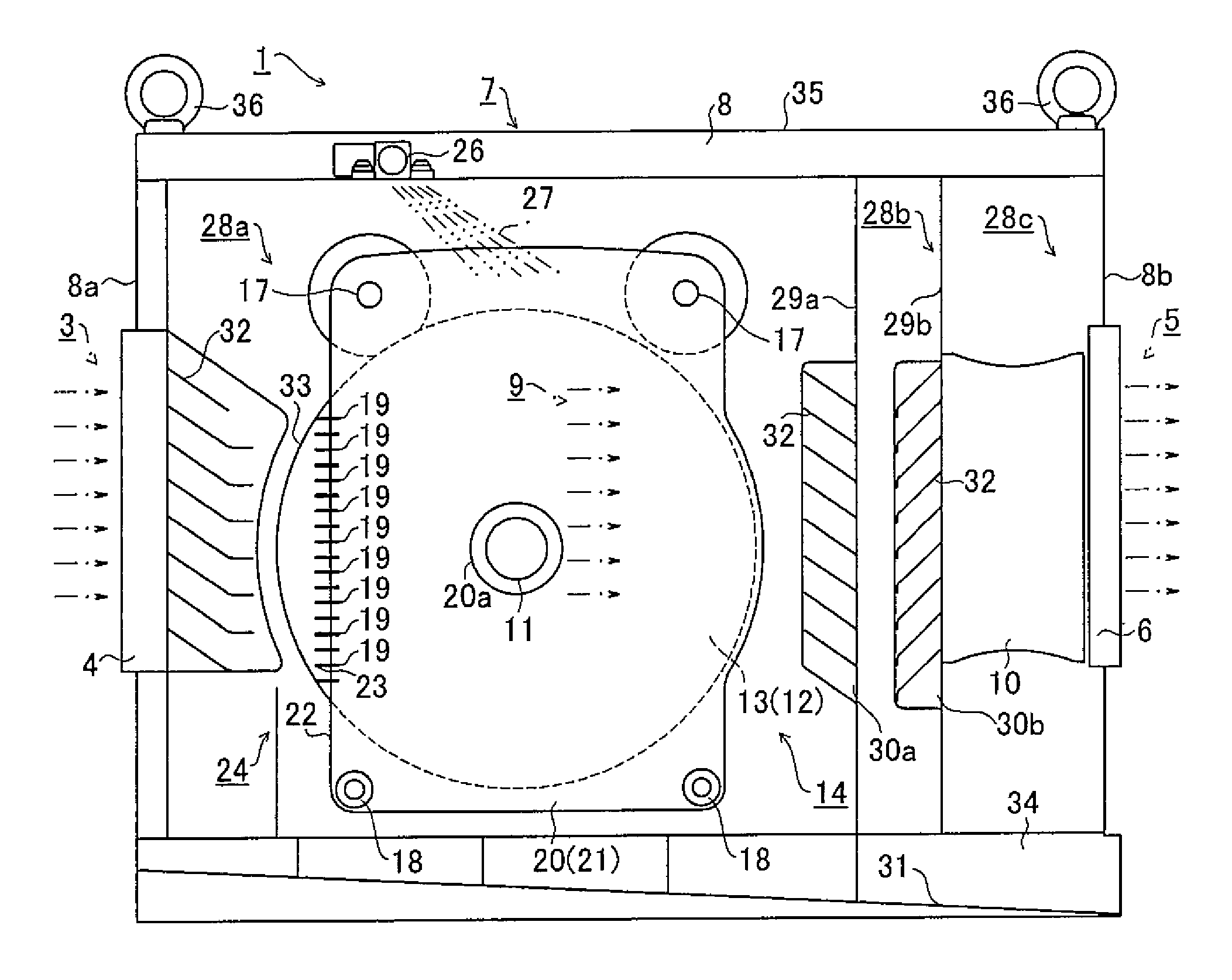
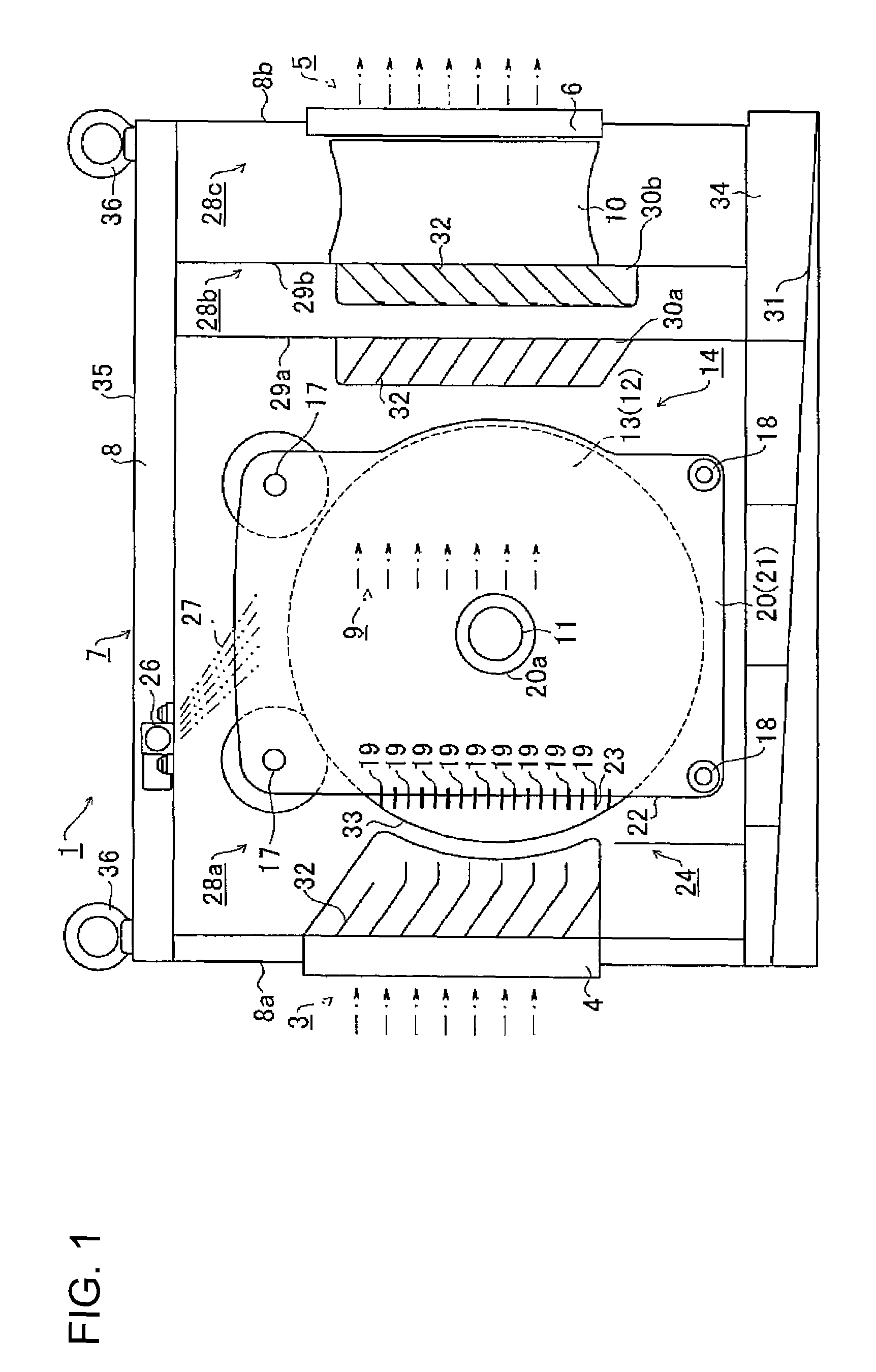
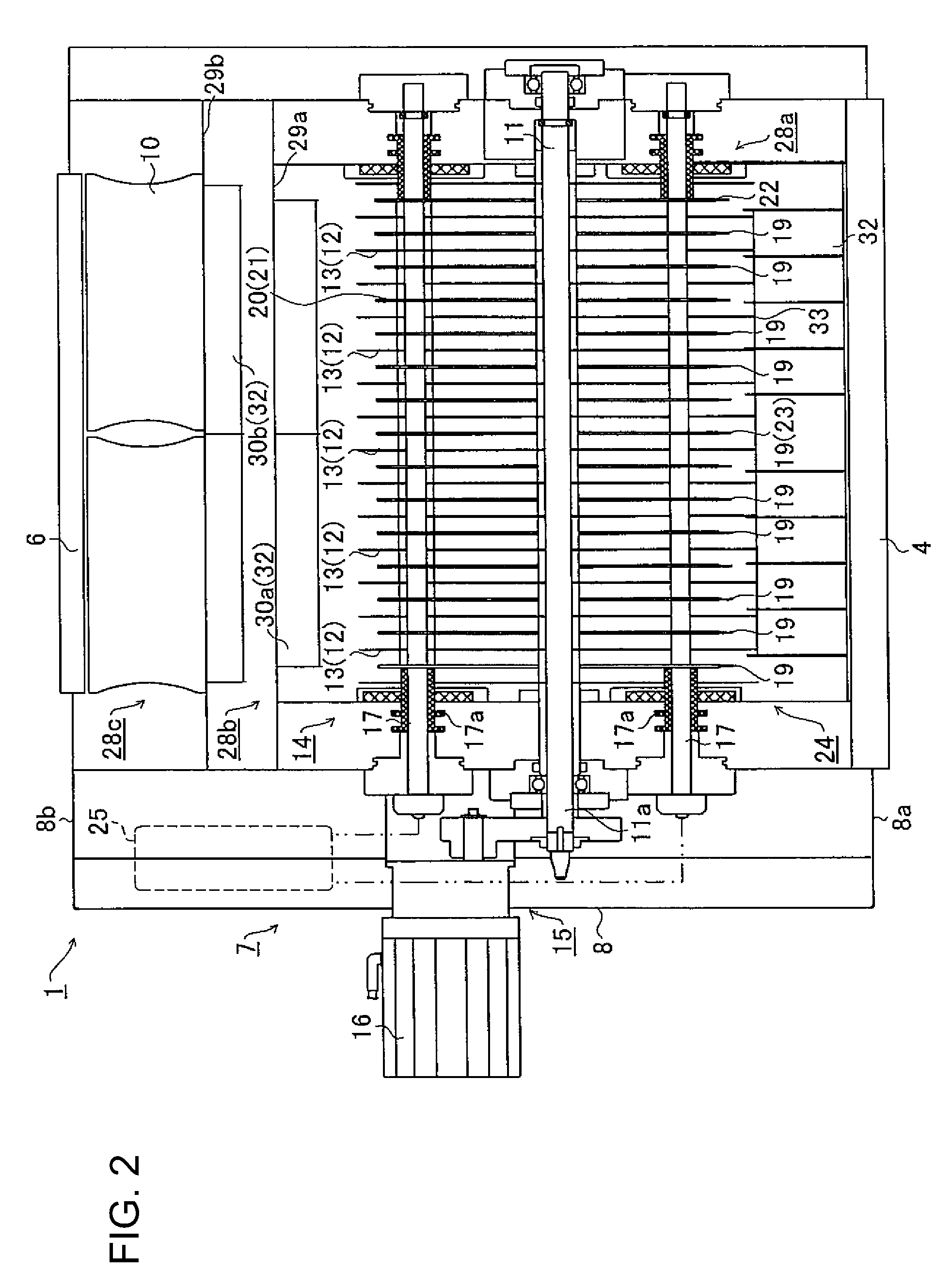
[0035]An electrostatic precipitator 1, one embodiment of the present invention, is described below with reference to FIGS. 1 through 4. Here, FIG. 1 is an explanation view showing the internal structure of the electrostatic precipitator of this type that is viewed from the side thereof. FIG. 2 is an explanation view showing the internal structure of electrostatic precipitator 1 that is viewed from the top thereof. FIG. 3 is an explanation view showing the structures of the discharge electrode, charging plates and adsorption plates. FIG. 4. is an explanation view illustrating the movements of charged particles.

[0036]An electrostatic precipitator of this embodiment mainly comprises a housing 8 inside of which an air duct 7 communicates between an inlet 4 sucking a contaminated air 3 that contains fine particles 2 and an outlet 6 discharging clean air 5 that has been cleaned through the electrostatic precipitator 1; an air flow generator 10 that is ...


PUM


Abstract

The electrostatic precipitator (1) includes the housing (8) having the air duct (7) for communicating between the inlet (4) for sucking the contaminated air (3) and the outlet (6) for discharging the cleaned air (5), the air flow generator (10) generating the air flow (9) in the air duct (7), the collecting section (14) having a plurality of adsorption plates (13) rotating in accordance with the adsorption shaft (11), and the discharge section (24) equipped with the charging plate (20) having the discharge surface (21) opposing the adsorption surface (12) of the adsorption plate (13) and a plurality of the discharge electrodes (19) provided at the edge (22) of the charging plate (20) opposite the suction inlet. The fine particles (2) contained in the contaminated air (3) are charged by the corona discharge (CD) generated from the pointed ends (23) of the discharge electrodes (19) and collected by using the Coulomb force while varying the relative positional relationship between fine particles (2) and the adsorption surface (12) at all times by the rotating of the adsorption plate (13).

Description

[0001]This application is the national stage of International Application No. PCT / JP2005 / 010778, filed on Jun. 13, 2005.BACKGROUND OF THE INVENTION[0002]1. Field of the Invention[0003]The present invention relates to an electrostatic precipitator, in particular an electrostatic precipitator that is capable of collecting fine particles that have been charged by corona discharge by rotating adsorption plates.[0004]2. Description of Related Arts[0005]Traditionally, so-called “industrial waste gases”, such as exhaust from boilers at industrial installations and a large quantity of soot discharged from power stations, before their release into the atmosphere, have been on occasion subjected to an air cleaning process to remove fine particles that may pollute the atmosphere (such as mist and dust containing various powdery or oily substances and moisture from industrial waste gases). The release of industrial waste gases containing these particles directly into the atmosphere poses a seri...

Claims


Application Information

Patent Timeline
Patent Type & Authority Patents(United States)
IPC IPC(8): B03C3/10
CPCB03C3/08B03C3/10B03C3/16B03C3/78B03C3/365B03C3/47B03C3/363Y02A50/2351B03C3/41
Inventor FURUTA, MASATOSHIOHKURA, SHIGENOBU
Owner ZESU GIKO
Why Eureka
Try Eureka