
Method and apparatus for measuring duty cycle

a duty cycle and measurement method technology, applied in the field of systems, can solve the problems of not being able to use factory calibration information, assume well-shaped waveforms, and not being able to optimize the performance of very high-speed signal processing, and achieve accurate and efficient measurement of the duty cycle of an input signal

Inactive Publication Date: 2010-01-05
TEKTRONIX INC
View PDF10 Cites 17 Cited by
  • Summary
  • Abstract
  • Description
  • Claims
  • Application Information

AI Technical Summary

Benefits of technology

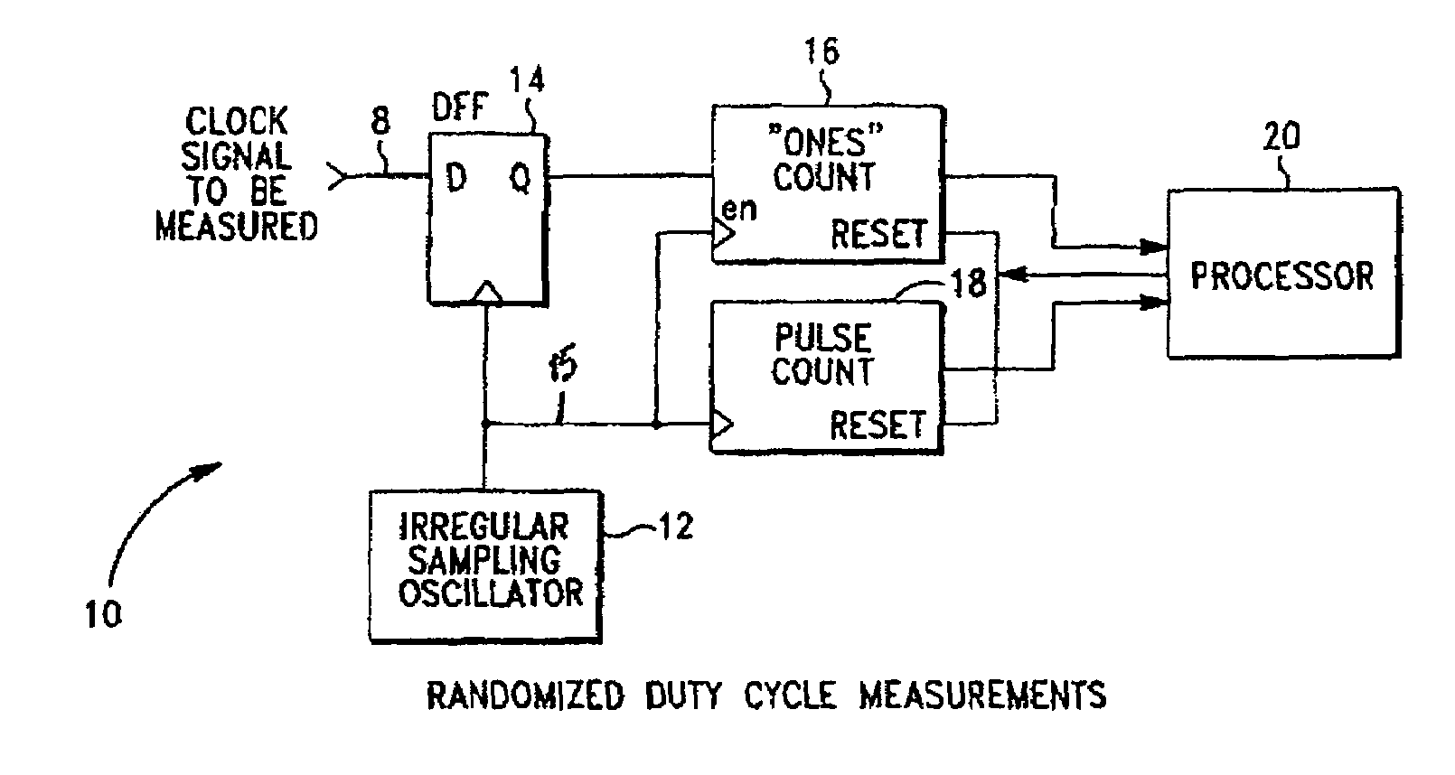
The present invention provides a method and structure for accurately and efficiently measuring the duty cycle of an applied input signal by sampling the signal with a sampling clock that has a lower frequency than the input signal. The sampling clock is not synchronous with the input signal, which ensures that the sampled data values represent the averaged 1- and 0-levels. The invention uses a flip flop, a derived sampling clock, a low-pass filter, or digital counters for voltage averaging, depending on the application. The invention provides a more accurate and efficient measure of duty cycle than previous methods and can adjust to changes in the input signal frequency.

Problems solved by technology

Both interpretations can lead to non-optimal performance of very high speed signal processing if the duty cycle deviates from tolerable levels.
In some systems, however, the application space is so broad, that it is not possible to use factory calibration information as it is not relevant to the then current environment.
The problem with this method is that it assumes well-shaped waveforms.
Making assumptions about the shape of the wave form results in inaccuracies.

Method used


Image

  • Method and apparatus for measuring duty cycle
  • Method and apparatus for measuring duty cycle

Examples


Embodiment Construction

[0027]The invention will now be described in greater detail with reference to the accompanying drawings, in which the exemplary embodiments of the invention are shown. The present invention may, however, be embodied in many different forms and should not be construed as limited to the embodiment set forth herein; rather these embodiments are provided so that this disclosure will be thorough and complete and will fully convey the invention to those skilled in the art.

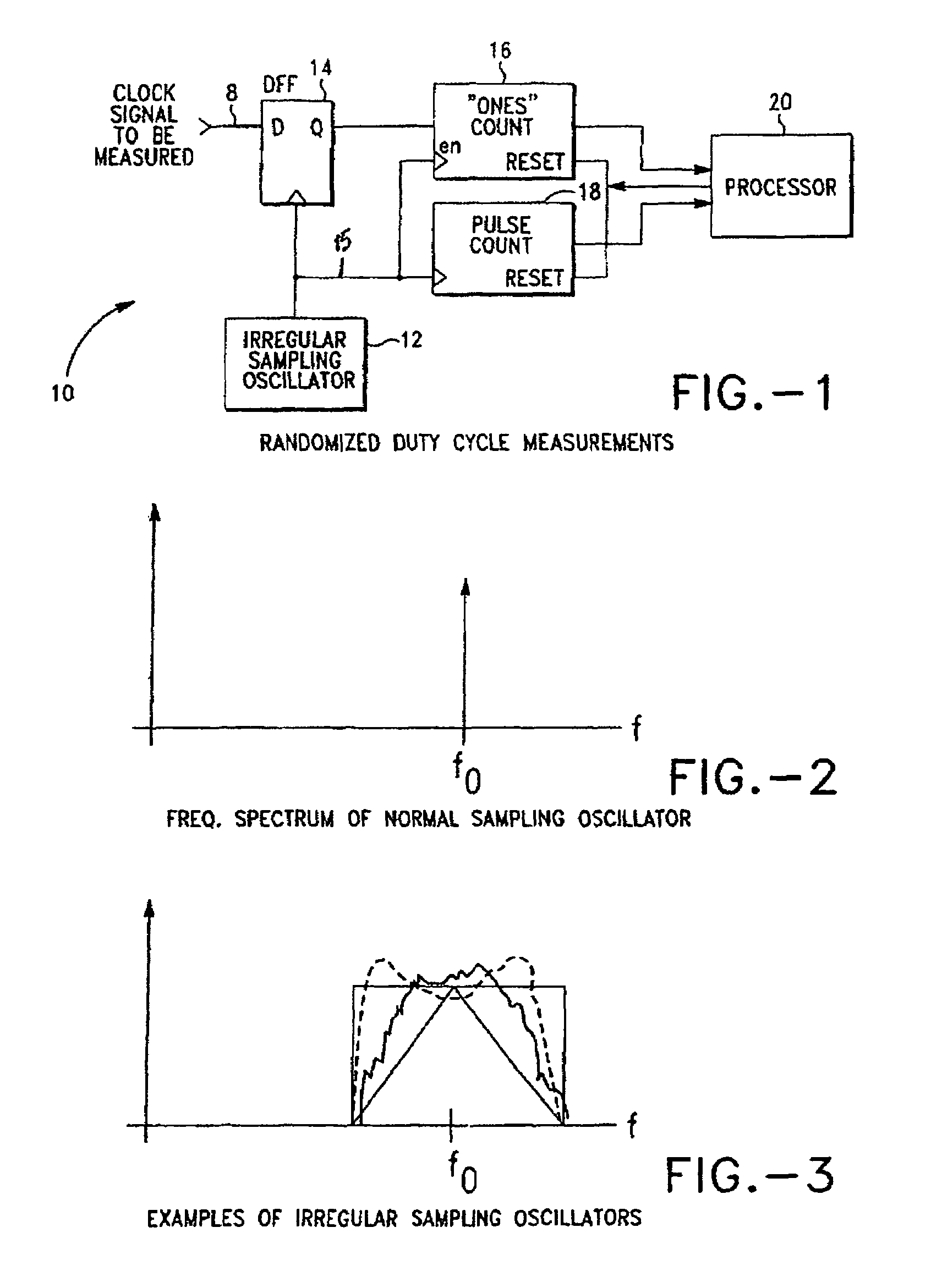
[0028]FIG. 1 is a schematic representation of the invention, a measuring device. The invention measures the duty cycle of a high-frequency clock signal 8 with very minimal hardware. The measuring device accomplishes its objectives by utilizing an irregular (non-coherent) sampling clock oscillator and straightforward flip flops, counters and processing elements.

[0029]The measuring device will now be described with respect to FIGS. 1-3, which illustrates an exemplary embodiment of the invention shown generally by the numer...


PUM


Abstract

Disclosed herein is a method and apparatus used to the measure duty cycle of a clocking waveform utilizing minimal hardware and achieving high accuracy. This invention utilizes digital sampling of the signal to be measured at a rate that can be significantly lower then the clocking frequency of the signal to be measured. It accomplishes broad-band, multi-frequency use by using a time-varying frequency for the sampling clock to make sure that the sampling clock is asynchronous with the frequency of the clocking signal to be measured. The average ratio of the sampled ones (or zeros) as compared to the total number of samples is then computed to derive the measurement of duty cycle.

Description

BACKGROUND OF THE INVENTION[0001]1. Field of the Invention[0002]This invention relates to systems which measure the duty cycle of a periodic signal. More particularly, this invention relates to a circuit and various components which measure the duty cycle of a periodic signal with great accuracy.[0003]2. Description of the Related Art[0004]The duty cycle, in electronic signals, is often expressed as a percentage of duration of a 1-level compared to the total duration of a complete 1-0 cycle. The duty cycle is an expression of the average DC energy of a clocking signal introduced by the duty cycle. A 50% duty cycle has average DC energy of one-half the difference of the 1-level and the 0-level as there is an equal duration of 1-level signal and 0-level signal. The duty cycle in clocking waveforms is also a measure of second harmonic energy in a clocking signal which can appear as a deterministic jitter source from odd-even pulse widths in the clocking signal. Both interpretations can...

Claims


Application Information

Patent Timeline
Patent Type & Authority Patents(United States)
IPC IPC(8): G01R13/02
CPCG01R29/0273
Inventor WILLIS, ANDRE
Owner TEKTRONIX INC
Learn More