Remote management of portable construction devices

Active Publication Date: 2010-01-05
LINCOLN GLOBAL INC
View PDF30 Cites 144 Cited by
  • Summary
  • Abstract
  • Description
  • Claims
  • Application Information

AI Technical Summary

Benefits of technology

[0006]The present invention relates generally to portable construction devices and, more particularly, to systems and methods for remotely managing portable welding systems on a construction site. A co-located communication component is leveraged to provide remote management of a portable construction device such as, for example, a welding unit. This provides a means to monitor and/or control the portable construction device from a central management site such as, for example, a construction job site office. The communication component allows the central site, and/or another communication component, to interact with the portable construction device to retrieve such information as, for example, usage information and/or status information. The communication component also allows remote control of the devices such as, for example, remote power control and/or control of auxiliary devices that facilitate the functionality of the portable construction devices. Communication with these devices facilitates such activities as distributed control, maintenance, customer support, and/or order/supply/distribution of weld

Problems solved by technology

Given the nature and requirements of modern and more complex construction operations however, welding systems designers, architects and suppliers face increasing challenges in regard to upgrading, maintaining, controlling, servicing and supplying various welding locations.
Unfortunately, many conventional welding systems operate in individually controlled and somewhat isolated locations in regard to the overall construction pr

Method used


Image

  • Remote management of portable construction devices
  • Remote management of portable construction devices
  • Remote management of portable construction devices

Examples


Embodiment Construction

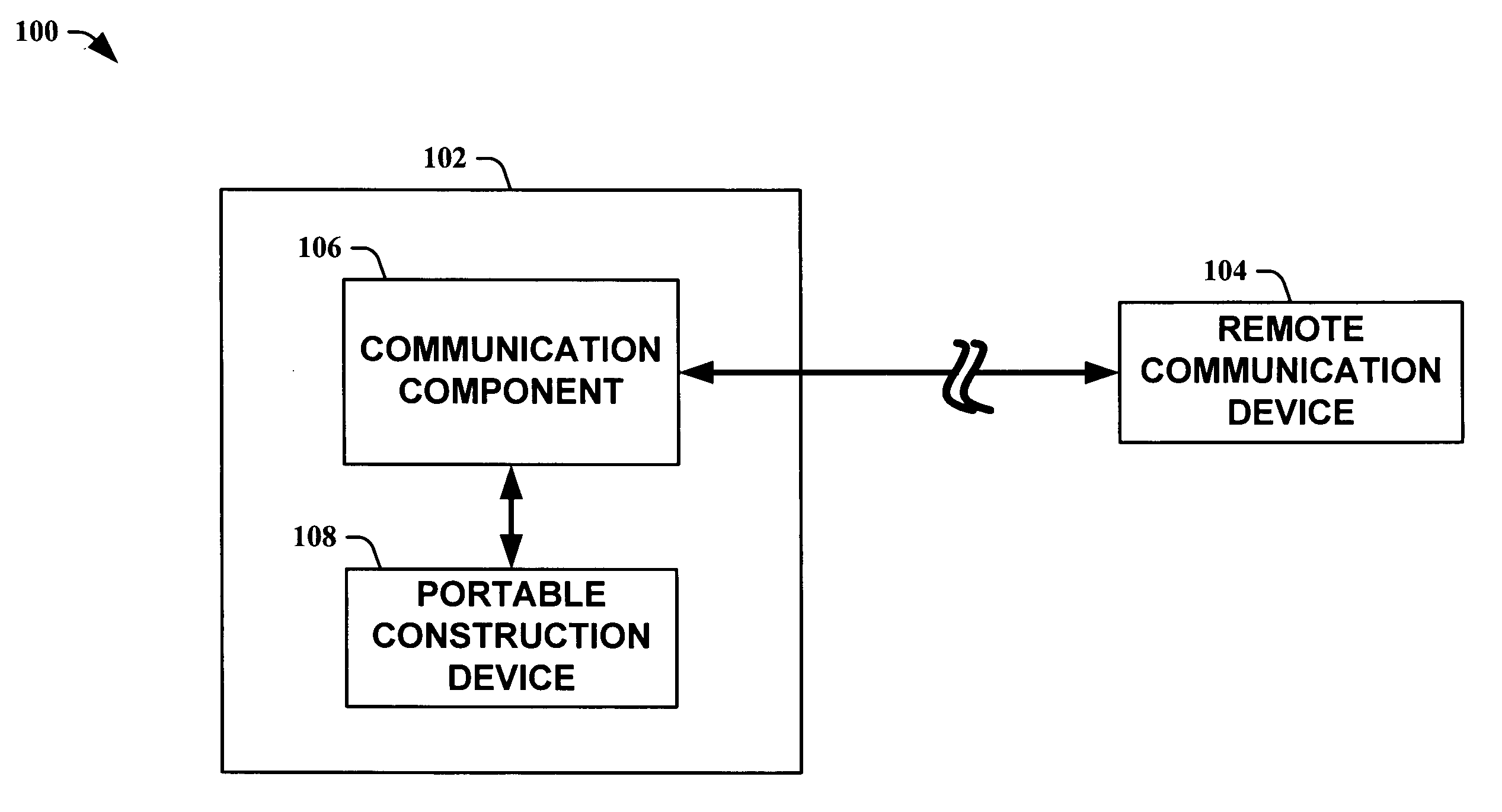
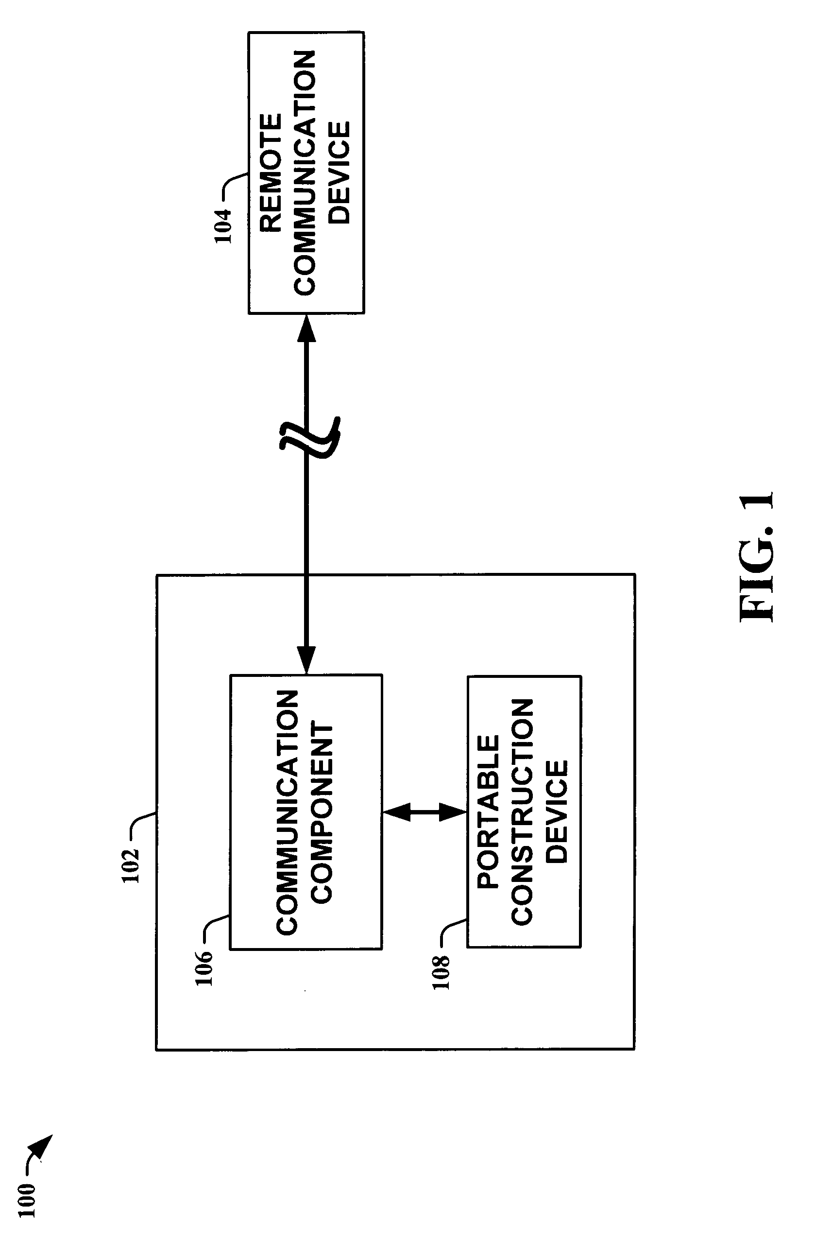
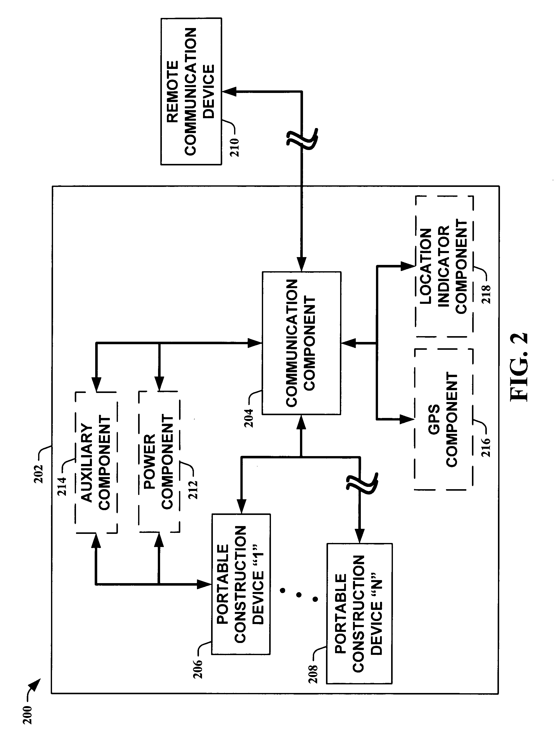
[0017]The present invention is now described with reference to the drawings, wherein like reference numerals are used to refer to like elements throughout. In the following description, for purposes of explanation, numerous specific details are set forth in order to provide a thorough understanding of the present invention. It may be evident to one skilled in the art that the present invention may be practiced without these specific details. In other instances, well-known structures and devices are shown in block diagram form in order to facilitate description of the present invention.

[0018]As used in this application, “system” is a structure comprising one or more components. A “component” is a structure comprising computer hardware and / or software. For example, a component can be, but is not limited to, a computer readable memory encoded with software instructions or a computer configured to carry out specified tasks. By way of illustration, both an application program stored in c...


PUM

PropertyMeasurementUnit
Poweraaaaaaaaaa
Distanceaaaaaaaaaa
Levelaaaaaaaaaa

Abstract

The present invention leverages a co-located communication component to provide remote management of a portable construction device. This enables monitoring and/or controlling the portable construction device from a central management site. The communication component allows the central site, or another communication component, to interact with the portable construction device to retrieve information such as, for example, usage information and/or status information. The communication component also allows remote control of the devices such as, for example, remote power control and/or control of auxiliary devices that facilitate the functionality of the portable construction devices. The present invention can also incorporate global positioning systems and/or location indicating systems to facilitate in determining where the portable construction devices are located and/or when the devices are properly positioned. The systems themselves can be distributed to form a communication network with bi-directional communication capabilities.

Description

TECHNICAL FIELD[0001]The present invention relates generally to portable construction devices and, more particularly, to systems and methods for remotely managing portable welding systems on a construction site.BACKGROUND OF THE INVENTION[0002]Welding systems reside at the core of the modern industrial age. From massive automobile assembly operations to automated manufacturing environments, these systems facilitate joining in ever more complicated manufacturing operations. One such example of a welding system includes an electric arc welding system. This may involve movement of a consumable electrode, for example, toward a work piece while current is passed through the electrode and across an arc developed between the electrode and the work piece. The electrode may be a non-consumable or consumable type, wherein portions of the electrode may be melted and deposited on the work piece. Often, hundreds or perhaps thousands of welders are employed to drive multiple aspects of a construc...

Claims


Application Information

Patent Timeline
IPC IPC(8): G05B23/02G01C9/00G05D1/10G08B17/06G08B5/22G06F11/00G05B11/01G05B15/00G05B19/00
CPCB23K9/0953B23K9/1087B23K9/1062
Inventor HILLEN, EDWARD D.KAINEC, STEPHEN M.MATTHEWS, WILLIAM T.
Owner LINCOLN GLOBAL INC
Why Eureka
Try Eureka