Humidity sensor having humidity sensitive film and method for manufacturing the same

a technology of humidity sensitive film and humidity sensor, which is applied in the direction of material analysis, instruments, and using mechanical means, can solve the problems of affecting the sensitivity of the above sensor, and achieve the effects of reducing the manufacturing cost of the sensor, improving the sensitivity of the sensor, and reducing the variability of the sensor sensitivity

Inactive Publication Date: 2010-01-12
DENSO CORP
View PDF11 Cites 12 Cited by
  • Summary
  • Abstract
  • Description
  • Claims
  • Application Information

AI Technical Summary

Benefits of technology

[0010]In the above sensor, since the height of the humidity sensitive film in the groove is homogeneous, the thickness of the humidity sensitive film is also homogeneous. Accordingly, thickness variation of the humidity sensitive film is small, so that variation of sensor sensitivity is reduced. Further, the above groove provides a dam structure for accommodating the humidity sensitive film, so that a manufacturing cost of the sensor is reduced. Furthermore, since the humidity sensitive film is exposed from the mold, the sensor sensitivity is improved.
[0012]In the above method, the humidity sensitive film is easily formed in the groove without forming an additional dam structure. Thus, the manufacturing cost of the sensor is reduced. Further, the humidity sensitive film is easily arranged at a predetermined position, i.e., in the groove, and the height of the humidity sensitive film in the groove is easily uniformed. Thus, the thickness variation of the humidity sensitive film is reduced, so that sensor sensitivity variation is reduced.
[0015]In the above sensor, since the height of the humidity sensitive film in the groove is homogeneous, the thickness of the humidity sensitive film is also homogeneous. Accordingly, thickness variation of the humidity sensitive film is small, so that variation of sensor sensitivity is reduced. Further, the above groove provides a dam structure for accommodating the humidity sensitive film, so that a manufacturing cost of the sensor is reduced. Furthermore, since the humidity sensitive film is exposed from the mold, the sensor sensitivity is improved.

Problems solved by technology

Thus, the sensitivity of the above sensor is much affected by thickness deviation of the humidity sensitive film.

Method used


Image

  • Humidity sensor having humidity sensitive film and method for manufacturing the same
  • Humidity sensor having humidity sensitive film and method for manufacturing the same
  • Humidity sensor having humidity sensitive film and method for manufacturing the same

Examples


Embodiment Construction

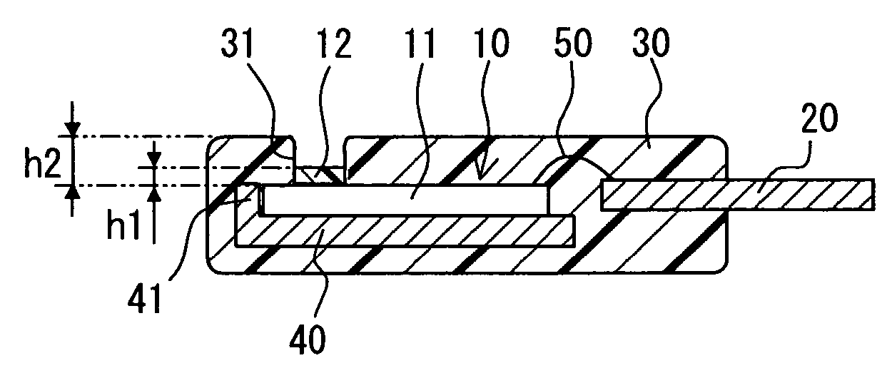
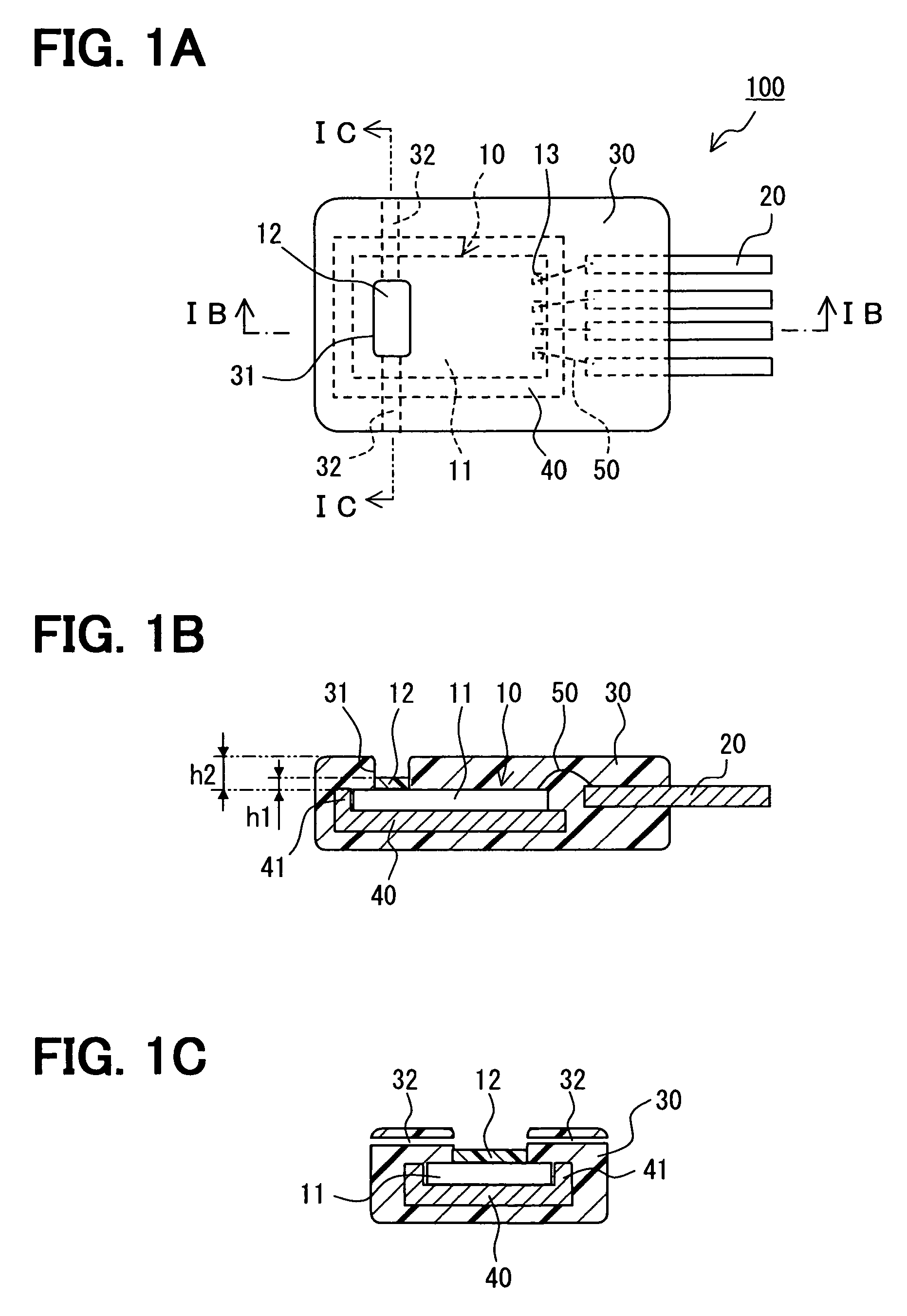
[0020]FIGS. 1A to 1C show a humidity sensor 100 according to an example embodiment. The sensor 100 includes a sensor chip 10 having a capacitive humidity sensor element, a lead plate 20 for connecting to the sensor chip 10, a mold 30 for covering the connection portion between the sensor chip 10 and the lead plate 20, and a support member 40 for mounting the sensor chip 10 thereon.

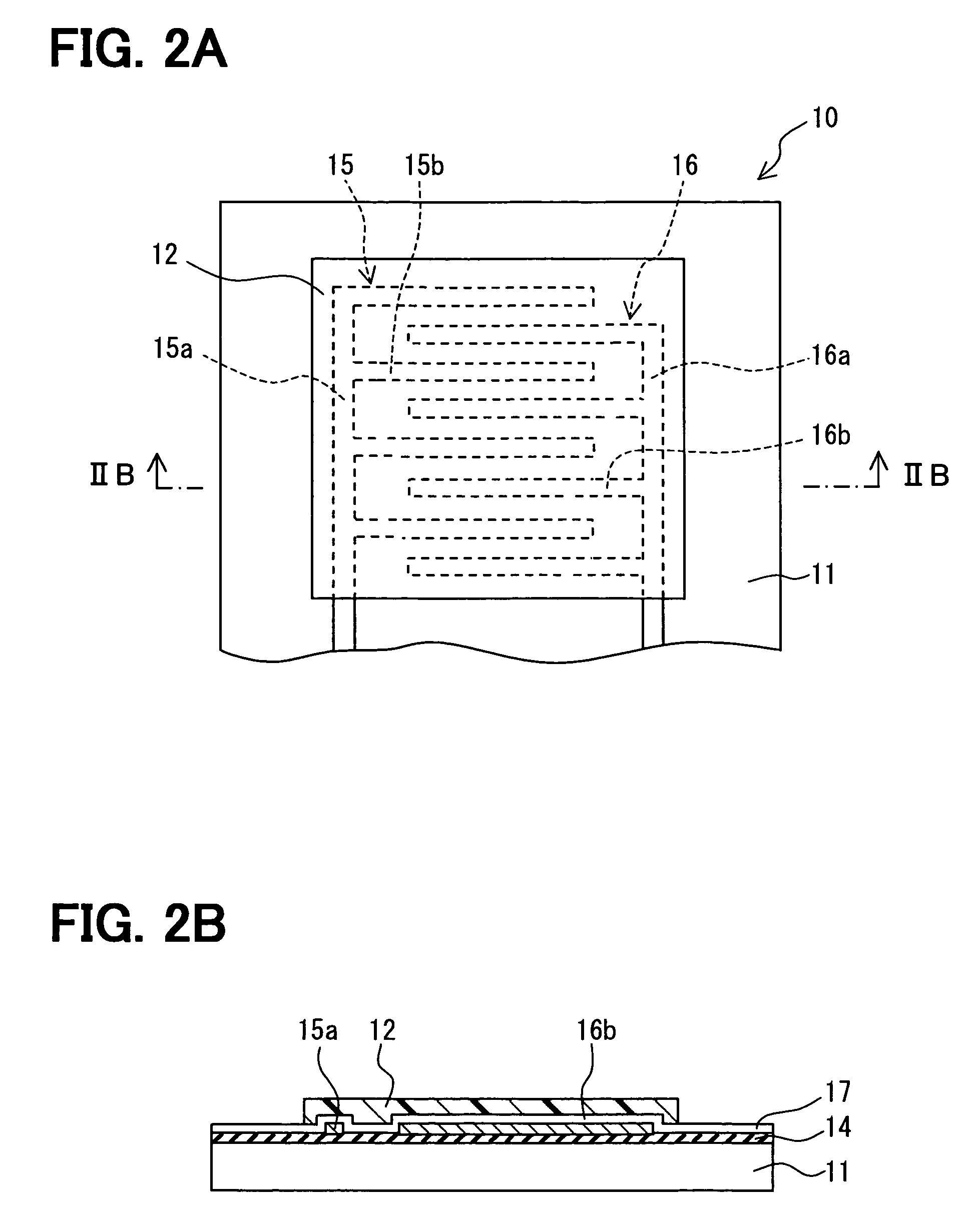
[0021]The sensor chip 10 includes a silicon substrate 11, a humidity sensitive film 12 disposed on the substrate 11, an electrode pad 13. The relative permittivity of the humidity sensitive film 12 is changeable in accordance with humidity around the sensor 100. The electrode pad 13 is connected to the humidity sensor element electrically, and functions as an external connection terminal. The electrode pad 13 is electrically connected to the lead plate 20 through a bonding wire 50 so that a signal detected by the humidity sensor element is outputted to an external circuit through the lead plate 20. The lea...


PUM

PropertyMeasurementUnit
relative permittivityaaaaaaaaaa
viscosityaaaaaaaaaa
humidityaaaaaaaaaa

Abstract

A humidity sensor includes: a sensor chip including a capacitive humidity sensor element and a connection electrode, wherein the capacitive humidity sensor element includes a humidity sensitive film having relative permittivity changeable in accordance with humidity, and wherein the connection electrode is electrically connected to the humidity sensor element; a lead plate electrically connected to the connection electrode; and a mold for covering a connection portion between the connection electrode and the lead plate. The mold is disposed on the sensor chip and includes a groove. The humidity sensitive film is disposed in the groove. The humidity sensitive film has a height in the groove, the height equal to or lower than a surface of the mold. The height of the humidity sensitive film in the groove is homogeneous.

Description

CROSS REFERENCE TO RELATED APPLICATION[0001]This application is based on Japanese Patent Application No. 2005-322887 filed on Nov. 7, 2005, the disclosure of which is incorporated herein by reference.FIELD OF THE INVENTION[0002]The present invention relates to a humidity sensor having a humidity sensitive film and a method for manufacturing the same.BACKGROUND OF THE INVENTION[0003]Conventionally, a capacitive humidity sensor having a humidity sensitive film is disclosed in, for example, U.S. Pat. No. 6,580,600. The relative permittivity of the humidity sensitive film is changeable in accordance with humidity. The humidity sensitive film is disposed between a pair of electrodes.[0004]In the sensor, the electrodes are disposed on the same plan of a substrate, and face each other. The humidity sensitive film is disposed between the electrodes and covers the electrodes.[0005]In a manufacturing method of the above sensor, a paste including high polymer material is printed on the substra...

Claims


Application Information

Patent Timeline
Patent Type & Authority Patents(United States)
IPC IPC(8): G01N27/22
CPCG01N27/223H01L2224/48247
Inventor ARISAKA, NAOKI
Owner DENSO CORP
Why Eureka
Try Eureka