Ultra-wideband (UWB) antenna

a technology of ultra-wideband and antenna, applied in the direction of resonant antennas, antenna earthings, elongated active element feeds, etc., can solve the problems of affecting the commercialization of previously known devices, affecting the performance of antennae, and affecting the design of ultra-wideband antennas. , to achieve the effect of reducing the area of printed circuit boards, not affecting performance, and easy extension

Inactive Publication Date: 2010-01-12
NAT TAIWAN UNIV
View PDF7 Cites 30 Cited by
  • Summary
  • Abstract
  • Description
  • Claims
  • Application Information

AI Technical Summary

Benefits of technology

[0011]Compared with conventional prior art, the ultra-wideband (UWB) antenna according to present invention can provide the following advantages: (1) it can greatly reduce the area of the printed circuit board but do not affect its performance; (2) it can be easily extended to an antenna with the band-rejection function, but the original design of the antenna needs not to be changed; and (3) its co-plane feeding structure is simple in geometry and the parameters of the ultra-wideband (UWB) antenna can be adjusted by adjusting the length and width of the horizontal portion or the space between the lower edge of the horizontal portion of the co-plane feeding structure and the inner circumference of the rectangular aperture portion.

Problems solved by technology

Existing antenna designs for ultra-wideband technologies suffer from setbacks such as three-dimensional structure or large size.
The size of these antennae adversely affects the commercialization of the previously known devices.
The cost is high and the rejection of 802.11a RF signal in the 5-6 GHz band cannot be performed.
However, a structure with the U-shaped aperture, the first slot, and the second slot is complicated and thus difficult for mass production.

Method used


Image

  • Ultra-wideband (UWB) antenna
  • Ultra-wideband (UWB) antenna
  • Ultra-wideband (UWB) antenna

Examples


Embodiment Construction

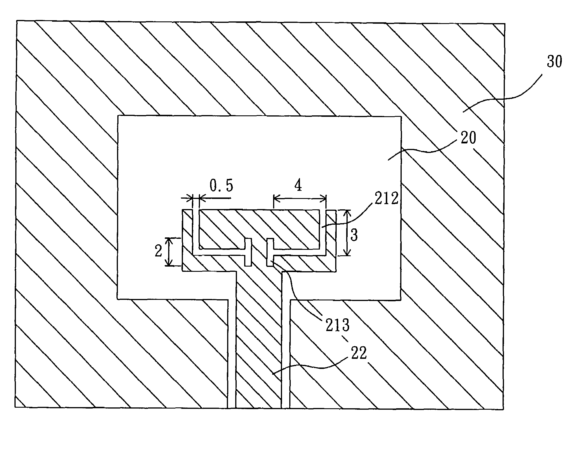
[0023]FIG. 4 schematically illustrates a preferred embodiment of an ultra-wideband (UWB) antenna according to the present invention, comprising a rectangular aperture portion 10, and a co-plane feeding structure 20.

[0024]The rectangular aperture portion 10 is formed from the ground plane of a printed circuit board 30 and has an aperture 11, wherein the printed circuit board 30 is, for example but not limited to, a single-sided PCB or bendable super-thin substrate. The present invention selects, but not limited to, a single-sided printed circuit board for purpose of explanation, so as to reduce manufacture cost.

[0025]The rectangular aperture portion 10 can be of any shape. In the present invention, the rectangular aperture portion 10 is taken as, but not limited to, a rectangular shape. The size of the rectangular aperture portion 10 is, for example but not limited to, 23 mm in length and 13 mm in width. The size of the aperture 11 is, for example but not limited to, 4.4 mm in width....


PUM


Abstract

The present invention relates to an ultra-wideband (UWB) antenna, which comprises: a rectangular aperture portion, formed from a ground plane of a printed circuit board and having an aperture; and a co-plane feeding structure, having a horizontal portion and a vertical portion, wherein the vertical portion is perpendicular to the horizontal portion, and the vertical portion is disposed in the aperture and connected with an external terminal. The ultra-wideband (UWB) antenna of the present invention can receive the wireless signal with 3.1˜10.6 GHz band, and have a very compact area (13 mm×23 mm) and is easy to be mass produced. Furthermore, a parasitism element can be added into the co-plane feeding structure, so as to reject the in-band interferences from the existing systems like 5˜6 GHz signals of wireless LAN.

Description

FIELD OF THE INVENTION[0001]The present invention relates to an ultra-wideband (UWB) antenna and, in particular, to an ultra-wideband (UWB) antenna which is compact, can reject the 5˜6 GHz signal, and is easy to be manufactured.BACKGROUND OF THE INVENTION[0002]The development of ultra-wideband (UWB) technology signals the advent of the incorporation of wireless technology with high-speed transmission. Ultra-wideband (UWB) technology provides enough bandwidth for a number of applications to utilize high-speed wireless transmissions over a relatively short distance. Some examples of these applications include digital media contents, high definition television images, 3 D video, and wireless internet gaming.[0003]Antenna design is crucial for ultra-wideband technologies. There are many important design considerations, such as size, radiation pattern stability, band rejection, and so forth. Existing antenna designs for ultra-wideband technologies suffer from setbacks such as three-dimen...

Claims


Application Information

Patent Timeline
Patent Type & Authority Patents(United States)
IPC IPC(8): H01Q1/38
CPCH01Q1/38H01Q1/48H01Q9/40H01Q13/106
Inventor LIN, YI-CHENGHUNG, KUAN-JUNG
Owner NAT TAIWAN UNIV
Why Eureka
Try Eureka