Particle and device for image display

a technology of image display and particle, applied in the field of image display devices, can solve the problems of lack of imaging repetition stability, slow response speed, difficult to maintain the stability of the dispersion state, etc., and achieve the effects of low electrostatic property, excellent image, and stable operation

Inactive Publication Date: 2010-01-12
BRIDGESTONE CORP
View PDF9 Cites 29 Cited by
  • Summary
  • Abstract
  • Description
  • Claims
  • Application Information

AI Technical Summary

Benefits of technology

[0015]As a result of the inventor's dedicated investigation, it is found that it is possible to obtain the particle having an excellent electrostatic property and achieving a decrease of the drive voltage by arranging a micro-irregularity on a surface of the particle, and, that it is possible to obtain stably the excellent image having a sufficient contrast since an incident light looks like a white color when viewing due to its irregular reflection, and the present invention is realized.

Problems solved by technology

However, in the electrophoresis method, there is a problem that a response speed is slow by the reason of viscosity resistance because the particles migrate among the electrophoresis solution.
Further, there is a problem of lacking imaging repetition stability, because particles with high specific gravity of titanium oxide is scattered within solution of low specific gravity, it is easy to subside, difficult to maintain a stability of dispersion state.
Even in the case of microencapsulating, cell size is diminished to a microcapsule level in order to make it hard to appear, however, an essential problem was not overcome at all.
However, the electrostatic property of the particle is normally under control of a material of the particle itself, and thus it is difficult to control it accurately by the particle itself.
However, in the case that they are used with the black particles in the image display device, a contrast ratio lacks and thus whiteness is decreased.
Therefore, the producing method becomes very complicated.
Further, in the case that the method mentioned above is utilized, it is normally difficult to control a particle size.
However, in this case, it is not possible to obtain the particles having a narrow particle size distribution if the classifying operation is not performed.
Moreover, since a mechanical grinding is performed so as to obtain the fine particles, it is difficult to obtain the particles having a particle size of 8 μm or less even if the fine particles having a particle size under the above level are to be obtained.

Method used


Image

  • Particle and device for image display
  • Particle and device for image display
  • Particle and device for image display

Examples


example 1

[0109]As white color particles, use was made of particles in which 0.2 wt % of hydrophobic silica (H3004, Hoechst Japan Ltd.) was added in a porous polymethyl methacrylate particles (MBP8, SEKISUI PLASTICS CO., LTD, the average particle diameter d(0.5) of 6.1 μm).

[0110]As black color particles, use was made of a circular polymethyl methacrylate particles (Techpolymer MBX-5B, SEKISUI PLASTICS CO., LTD., the average particle diameter d(0.5) of 5.6 μm).

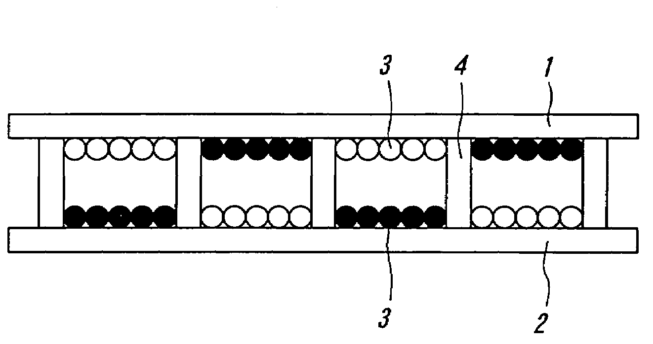
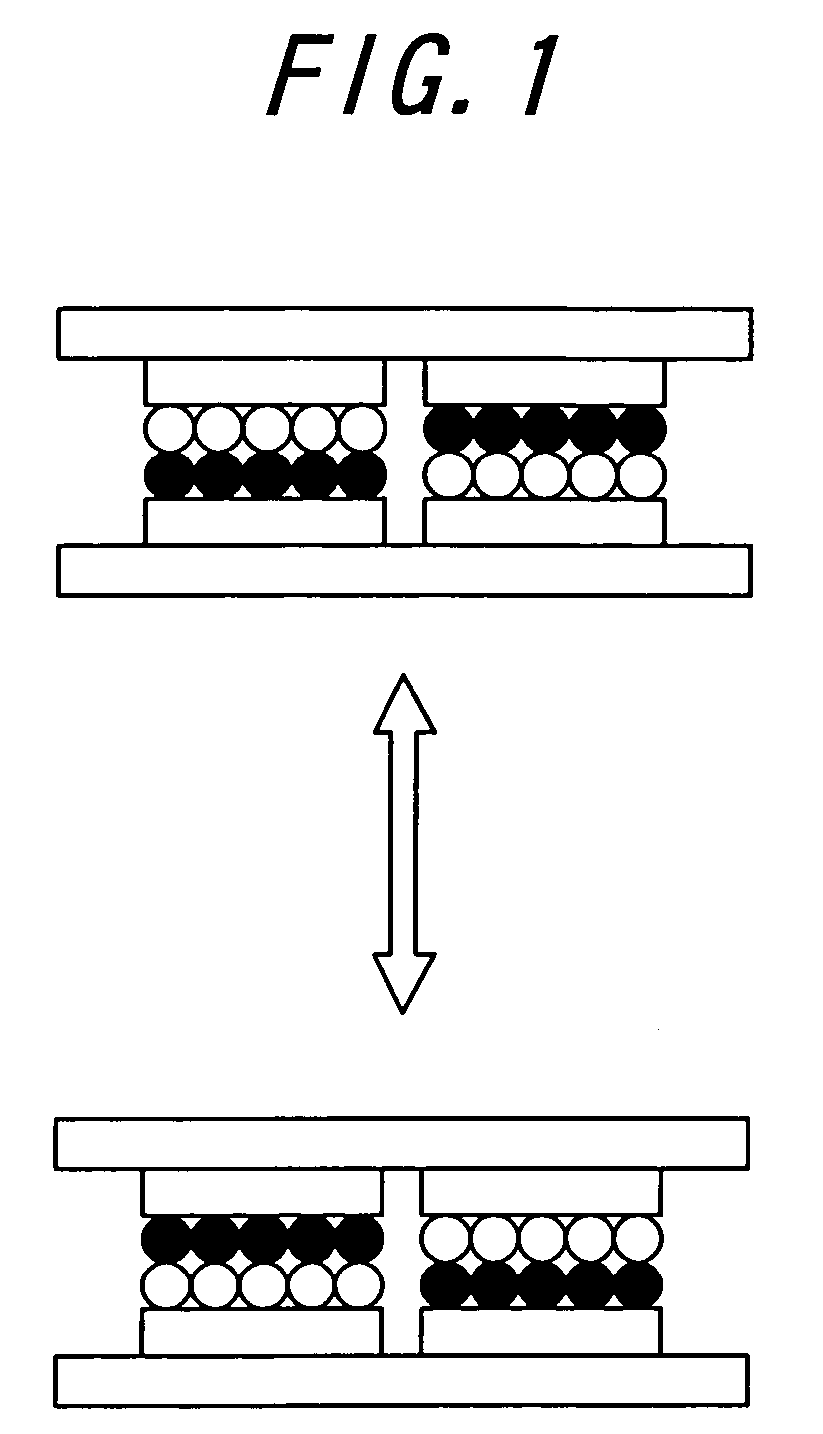
[0111]The display device was produced as follows. That is, a pair of glass substrates, on which indium oxide electrode having a thickness of about 500 Å (thickness: 50 nm), was assembled in such a manner that an interval between the substrates was controlled to be 100 μm by using spacers. Then, the white color particles and the black color particles mentioned above were filled in the space between the glass substrates, and peripheral portions of the glass substrates were connected by epoxy adhesive, so that the display device was produce...


PUM

PropertyMeasurementUnit
particle diameteraaaaaaaaaa
particle sizeaaaaaaaaaa
thicknessaaaaaaaaaa

Abstract

In particles for image displaying used in an image display device, in which one or more kind of particles are sealed between opposed substrates, at least one substrate being transparent, and, in which the particles are made to fly and move so as to display an image, each particle has a micro-irregularity at its surface. Moreover, in an image display device, in which one or more kind of particles are sealed between opposed substrates, at least one substrate being transparent, and, in which the particles, to which an electrostatic field produced by two kinds of electrodes having different potentials is applied, are made to fly and move so as to display an image, use is made of each particle having a micro-irregularity at its surface.

Description

TECHNICAL FIELD[0001]The present invention relates to an image display device, which comprises an image display panel enables to repeatedly display or delete images accompanied by flight and movement of particles utilizing Coulomb's force and so on.BACKGROUND ART[0002]As an image display device substitutable for liquid crystal display (LCD), image display devices with the use of technology such as an electrophoresis method, an electro-chromic method, a thermal method, dichroic-particles-rotary method are proposed.[0003]As for these image display device, it is conceivable as inexpensive visual display device of the next generation from a merit having wide field of vision close to normal printed matter, having smaller consumption with LCD, spreading out to a display for portable device, and an electronic paper is expected.[0004]Recently, electrophoresis method is proposed that microencapsulate dispersion liquid made up with dispersion particles and coloration solution and dispose the ...

Claims


Application Information

Patent Timeline
Patent Type & Authority Patents(United States)
IPC IPC(8): G02B26/00G02B26/08G02F1/29G02F1/1685
CPCG02F1/167G02F2001/1674G02F1/1671G02F1/1685
Inventor TAKAGI, KOJIMURATA, KAZUYANIHEI, NORIOYAKUSHIJI, GAKUKITANO, HAJIMEMASUDA, YOSHITOMOKAWAGOE, TAKAHIRO
Owner BRIDGESTONE CORP
Why Eureka
Try Eureka