Capper head

a technology of capper head and screw head, which is applied in the direction of caps, rotating screw stopper insertion, application, etc., can solve the problems of high production cost and outside, and achieve the effects of low cost, simple structure and preventing the unwinding of the tightened cap

Inactive Publication Date: 2010-01-19
TOYO SEIKAN KAISHA LTD
View PDF31 Cites 14 Cited by
  • Summary
  • Abstract
  • Description
  • Claims
  • Application Information

AI Technical Summary

Benefits of technology

[0009]Accordingly, the problem to be resolved is to obtain a simple structure for lowering a chuck, while rotating it, in a capper head for screwing a cap on the mouth section of a container by improving the internal structure, without relying on gears or a cam and a cam follower that are exposed to the outside and are expensive to produce, such as a fixed gear and lifting cam.
[0010]It is an object of the present invention to provide a capper head that does not use a fixed gear and a lifting cam to set the lifting stroke and timing thereof, as in the conventional capper heads, has a simple structure, and does not contaminate the environment.
[0012]With such capper head, when the servo motor is actuated, the rotation thereof is outputted to the motor output shaft. The rotation of the motor output shaft is transmitted to the screw mechanism. In the screw mechanism, the screw output shaft is rotated by the rotation of the motor output shaft and the screw action converts the rotation into the axial displacement. Because the chuck is linked to the screw output shaft, the chuck rotates, while holding the cap, whereby the cap is tightened on the mouth section of the container. Furthermore, the axial displacement of the screw output shaft can ensure the tightening action of the chuck, that is, sinking, while tightening the cap.
[0016]The capper head can comprise a fixed case that accommodates the screw mechanism, a seal member that seals an outlet port of the case which the screw output shaft passes through and extends, and an obstruction member that is provided in a portion of the screw output shaft that extends to outside of the case and abuts against the seal member when the screw output shaft is lifted to prevent permeation of liquid into said case when the chuck is washed. Because the chuck that clamps the cap is exposed to the outside of the fixed case accommodating the screw mechanism, contamination can adhere thereto, and it is desired that the chuck be cleaned periodically with a sterilization liquid or the like. Even when the outlet port of the case which the screw output shaft passes through and extends is sealed with the seal member, the sprayed sterilization liquid can permeate into the inside of the case through the seal under the pressure. Accordingly, it is preferred that the obstruction member be provided in the portion of the screw output shaft that extends to the outside of the case and return rotation is performed more than the regulated rotation of the servo motor, whereby the obstruction member be abutted against the seal member by the lift of the screw output shaft. Because a state is assumed in which the obstruction member is pressed against and covers the outside of the seal member, the permeation of the sprayed sterilization liquid into the case through the seal member can be prevented.
[0018]As described hereinabove, the capper head in accordance with the present invention comprises the sliding engagement section and screw mechanism between the servo motor and chuck. Therefore, the chuck descends correspondingly to the thread pitch of the cap, while rotating under the drive force of the servo motor, in the same manner as in the conventional structure. Because the capper head does not use a fixed gear and lifting cam that determine the lifting stroke and timing thereof in order to obtain such an actuation of the chuck, the capper head has a simple structure that can be realized at a low cost. Furthermore, when the stroke difference absorption section is provided at the screw output shaft, even when the thread pitch of the cap changes according to specifications or when an axial displacement occurs due to the mode of engagement of the thread peaks, the male threaded section and female threaded section as the tightening is started, the difference between the stroke provided by the screw mechanism and the stroke occurring in the chuck is automatically absorbed by the stroke difference absorption section. The servo motor may be driven by taking into account only the speed and torque of tightening. Thus, a capper head of high utility can be provided in which, even when the specifications of the cap, including the thread pitch, are changed, the replacement of the fixed gear and lifting cam that set the lifting stroke and timing thereof, which was necessary in the conventional capper heads, is unnecessary. Furthermore, when the screw output shaft is provided with a unidirectional clutch section, even when the outer peripheral surface of the cap is a taper-free cylindrical surface and the engagement with the chuck is not immediately released when the chuck starts to move up, the unwinding of the tightened cap can be prevented.

Problems solved by technology

Accordingly, the problem to be resolved is to obtain a simple structure for lowering a chuck, while rotating it, in a capper head for screwing a cap on the mouth section of a container by improving the internal structure, without relying on gears or a cam and a cam follower that are exposed to the outside and are expensive to produce, such as a fixed gear and lifting cam.

Method used


Image

  • Capper head
  • Capper head
  • Capper head

Examples


Embodiment Construction

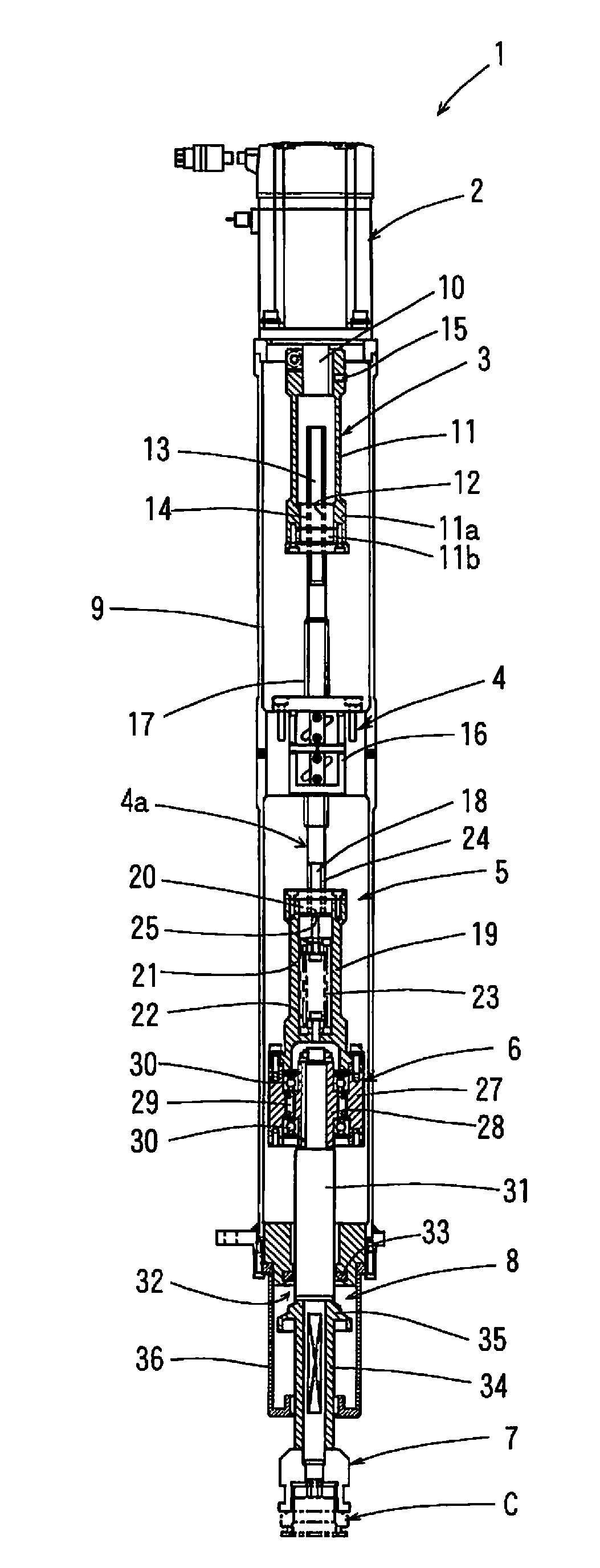
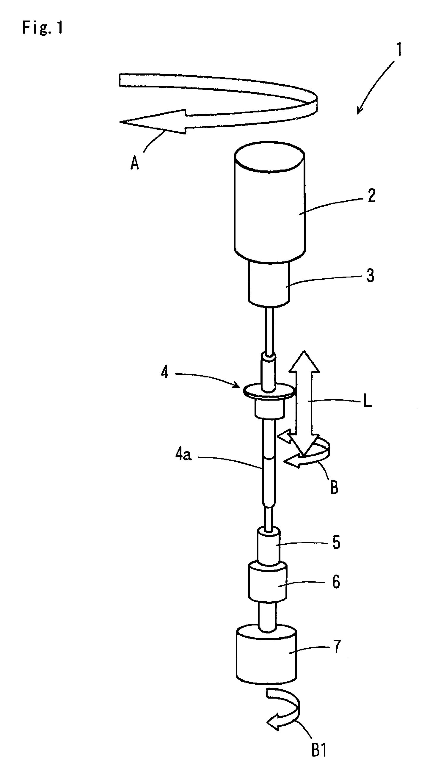
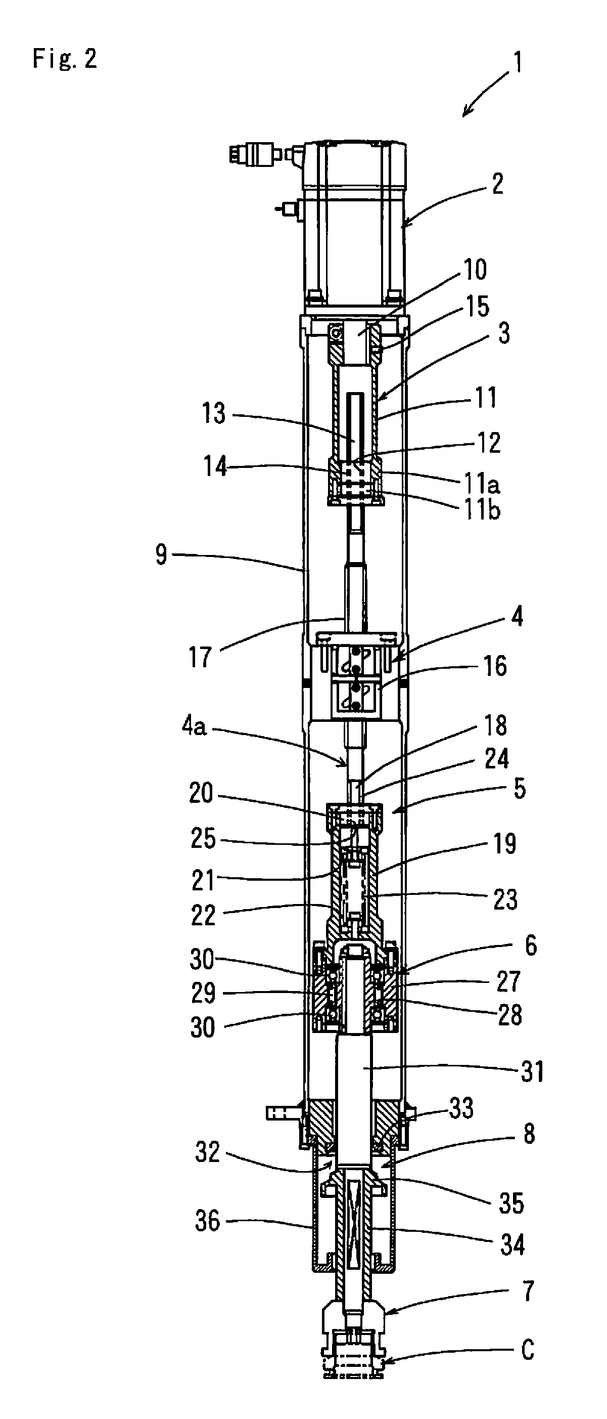
[0024]An embodiment of the capper head in accordance with the present invention will be described below based on the appended drawings. FIG. 1 is a schematic perspective view illustrating an embodiment of the capper head in accordance with the present invention. FIG. 2 is a vertical cross-sectional view of the capper head shown in FIG. 1.

[0025]As shown in FIG. 1, a capper head 1 comprises, from the top thereof, a servo motor 2 that is revolved and rotated, a sliding engagement section 3 that transmits the rotation of a motor output shaft of the servo motor 2, but allows the engagement portion to move in the axial direction and can be extended as a whole, a screw mechanism 4 linked to the output side of the sliding engagement section 3, and a chuck 7 linked to a screw output shaft 4a of the screw mechanism 4. The screw output shaft 4a is provided with a stroke difference absorption section 5 and a unidirectional clutch section 6 linked to the output side of the stroke difference abso...


PUM


Abstract

A capper head for general purpose usable even when the specifications of a cap including thread pitches are changed without using a fixed gear and a lifting cam determining a lifting stroke and the timing thereof. The rotational output of a servo motor (2) is transmitted to a screw mechanism (4) through a sliding engagement section (3), and a screw shaft (17) is lowered while rotating for capping. The lowering stroke of the screw shaft (17) is allowed by the sliding engagement section (3). In capping, even if the strokes of a rotating chuck (7) and an output shaft (31) are different from the lowering stroke by the screw mechanism (4), a stroke difference absorption section (5) absorbs the stroke difference therebetween since a spring (23) in combination with a spline transmitting the rotation is deflected in the axial direction.

Description

TECHNICAL FIELD[0001]The present invention relates to a capper head for automatically screwing a cap clamped in a chuck onto a mouth section of a container, while rotating the cap.BACKGROUND ART[0002]A conventional capper head for screwing a cap onto a mouth section of a container is shown in FIG. 4. A capper head 40 shown in FIG. 4 comprises a fixed gear 41 that is fixed to a frame not shown in the figure, a planetary gear 42 that is engaged with the fixed gear 41 and revolves, while rotating, around the fixed gear 41, a sliding bearing 44 that is engaged with an output shaft 43 of the planetary gear 42 to transfer the rotation of the planetary gear 42 and is supported to as to be free to slide in the axial direction relative to a rotary frame not shown in the figure, a torque limiter 45 that is linked to the output side of the sliding bearing 44 and restricts the upper limit of a tightening torque, and a chuck 46 that is linked to the output side of the torque limiter 45 and rotat...

Claims


Application Information

Patent Timeline
Patent Type & Authority Patents(United States)
IPC IPC(8): B67B1/06B67B3/20B67B3/18
CPCB67B3/18B67B3/2033
Inventor UEDA, NOBUYUKITAKEUCHI, KENJI
Owner TOYO SEIKAN KAISHA LTD
Why Eureka
Try Eureka