Approach for indicating the occurrence of a mechanical impact on a material, such as a low-ductility composite material

a composite material and mechanical impact technology, applied in the field of composite materials, can solve the problem of low degree of mechanical impact sensitive methods, achieve the effects of improving inspection techniques, easy detection, and good adhesion of paint to surfaces

Active Publication Date: 2010-01-19
SPECTRUM AERONAUTICAL
View PDF42 Cites 30 Cited by
  • Summary
  • Abstract
  • Description
  • Claims
  • Application Information

AI Technical Summary

Benefits of technology

[0015]The present approach thus provides a reliable approach for indicating the presence of a mechanical impact on the material such as the low-ductility material. The occurrence of such a mechanical impact may be readily detected visually, for example during a manufacturing operation, a periodic internal inspection by mechanics, or a pre-flight walk-around examination of the aircraft. Further investigation of any colored area (or other visual indicator) that is seen is thereafter performed as needed. Repair or corrective measures may then be taken as appropriate. The information gained from this approach may also be used in setting the design limits for the use of the low-ductility material. The information gained may also be used to improve inspection techniques by, for example, indicating impacted areas that need greater scrutiny during quality control inspection.
[0016]The present use of a paint-based indicator approach has many advantages. Paints are widely used and are familiar, so that the adoption of the present technique does not require that users accept a radically different approach than what is familiar. Paint technologies to ensure good adhesion of the paint to a surface, resistance to changes over time such as weathering, discoloration of the paint over time, good mechanical properties of the paint, surface smoothness of the paint, and the like are well established for other applications. The indicator paint, once applied, may remain in place for an extended period of time to protect the surface of the material in a manner like that of a conventional protective paint. The indicator paint functions in a passive manner in that the visual indicator only appears when impact occurs. Special instrumentation is not required to see the visual indication of the impact. A large area of the painted surface may be quickly scanned by eye to search for any possible visual indications, such as color changes, associated with the occurrence of an impact. There is a wide selection of types of visual indicator materials, such as many types of color producers that may be furnished in encapsulated form. The reactants that produce the visible change are enclosed within the paint, which protects them from weathering and other degradation. The amount of pigment in the indicator paint may be optimized for a combination of paint functionality and visibility of the impact indication.

Problems solved by technology

The method is sensitive to low levels of mechanical impact, even below levels that are normally considered to be damaging.

Method used


Image

  • Approach for indicating the occurrence of a mechanical impact on a material, such as a low-ductility composite material
  • Approach for indicating the occurrence of a mechanical impact on a material, such as a low-ductility composite material
  • Approach for indicating the occurrence of a mechanical impact on a material, such as a low-ductility composite material

Examples


Embodiment Construction

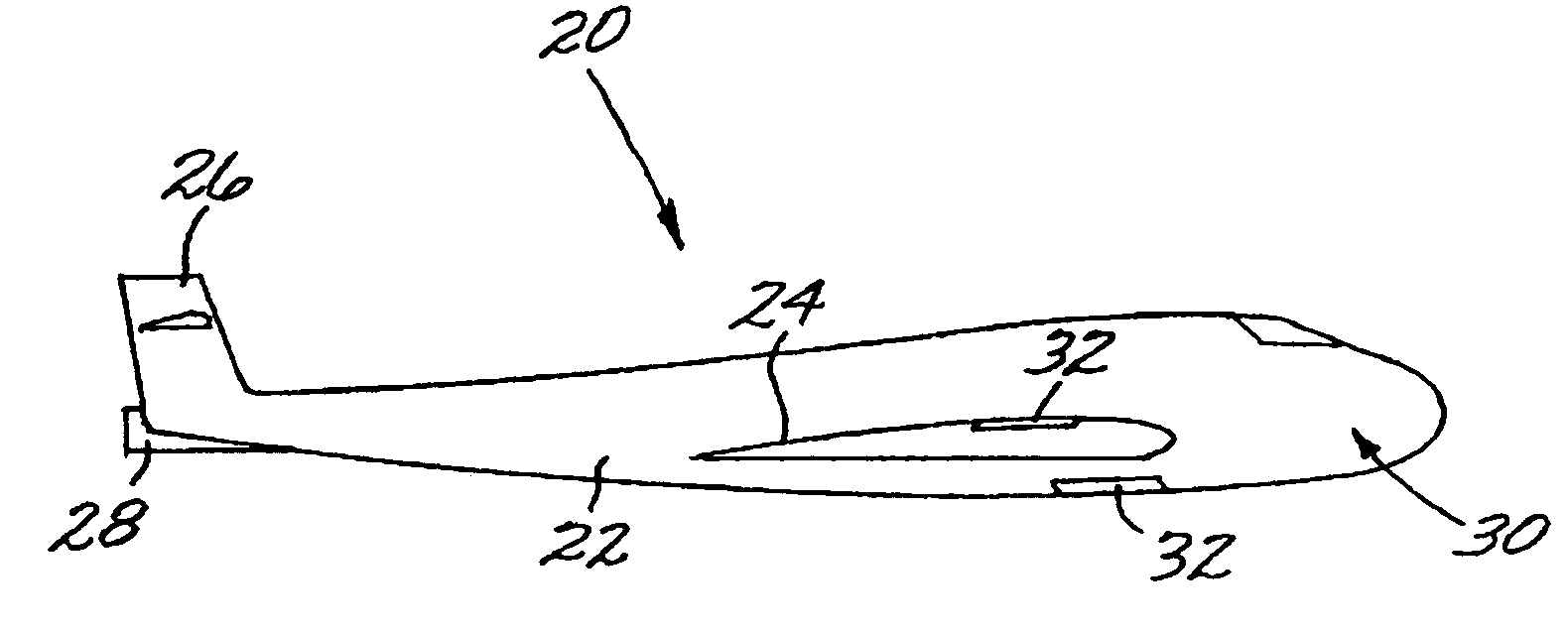
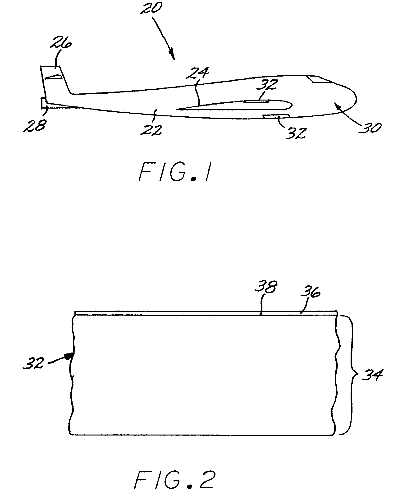
[0022]FIG. 1 depicts an aircraft 20 having a fuselage 22, a wing 24 attached to the fuselage 22, a tail 26 attached to the fuselage 22, and an engine 28 within the fuselage 22 (or which may be supported externally from some part of the fuselage 22, the wing 24, or the tail 26). Portions of an external surface 30 of the fuselage 22, the wing 24, or the tail 26 may be made of pieces, termed “panels”32 herein, of a material such as a low-ductility material, two of which panels are shown by way of example. Other portions of the aircraft 20, such as internal structure not visible in FIG. 1, may also be made of the low-ductility material. The preferred application of the present approach is in relation to such a low-ductility material. The remainder of the discussion will focus on the use with the low-ductility material, with the understanding that the present approach is applicable to higher-ductility materials as well.

[0023]FIG. 2 illustrates a portion of one of the panels 32 made of th...


PUM

PropertyMeasurementUnit
tensile elongation to failureaaaaaaaaaa
thickaaaaaaaaaa
tensile strengthaaaaaaaaaa

Abstract

A method of indicating the presence of mechanical impact is used with a low-ductility material, such as a composite material, having a tensile elongation to failure of less than about 2 percent. The method includes preparing an indicator paint having an impact-sensitive component that produces a visible change when subjected to a mechanical impact, applying the indicator paint to the surface of the low-ductility material, placing the low-ductility material having the indicator paint thereon into circumstances where it may be subject to the mechanical impact, and thereafter inspecting the low-ductility material having the indicator paint thereon for the presence of the visible change. The method may be used to establish design criteria for the low-ductility material by establishing an impact-effect threshold value from the step of inspecting, and determining a design limit for the low-ductility material responsive to the impact-effect threshold value. One result of the using the present approach is to reduce the structural weight by reducing the barely visible impact damage design factor.

Description

[0001]This invention relates to the detection of mechanical impacts on a material and to the utilization of the mechanical impact information in establishing design standards for use of the material.BACKGROUND OF THE INVENTION[0002]The widespread adoption of composite materials in aircraft structures has led to significant performance improvements. The composite material incorporates two or more component materials, each of which retains its individual identity, as phases into a single composite material. The resulting composite material is engineered to realize the most-advantageous properties of the various component materials, while minimizing or avoiding their disadvantageous properties.[0003]In a typical case, strong fibers are embedded in a polymeric matrix. An example of such a composite material includes carbon or graphite fibers embedded in a polymer matrix such as an epoxy. The high strength and modulus of the fibers are incorporated into the composite material. These mate...

Claims


Application Information

Patent Timeline
Patent Type & Authority Patents(United States)
IPC IPC(8): G01N3/30
CPCB64F5/0045G01L5/0052G01M5/0091G01M11/081B64F5/60
Inventor COONEY, DANIEL E.
Owner SPECTRUM AERONAUTICAL
Why Eureka
Try Eureka