Baffle plate, apparatus for producing the same, method of producing the same, and gas processing apparatus containing baffle plate

a technology of baffle plate and baffle duct, which is applied in the direction of chemical/physical/physico-chemical processes, chemistry apparatus and processes, coatings, etc., can solve the problems of increasing the pressure in the chamber, affecting the variation of differential pressure, and reducing the efficiency of the gas processing apparatus,

Inactive Publication Date: 2010-01-19
TOKYO ELECTRON LTD
View PDF31 Cites 40 Cited by
  • Summary
  • Abstract
  • Description
  • Claims
  • Application Information

AI Technical Summary

Benefits of technology

[0018]The above objects of the present invention are also achieved by a baffle plate that parts a process space in which a chemical process is carried out with a supplied gas from a duct that is adjacent to the process space for discharging an exhaust gas generated as a result of the chemical process. In this baffle plate, through holes are formed at a plurality of locations on the baffle plate, depending on pressure differences between two sides of the baffle plate. With this baffle plate, uniform exhaust required for the chemical process can be surely achieved.

Problems solved by technology

However, in a conventional technique of forming the identical baffle holes 7 on the baffle plate 9 at uniform intervals, it is difficult to obtain uniform exhaust flow 13 at every circumferential angle of the wafer 1.
As a result, the adverse influence of the inner pressure of the exhaust duct 5 on the variation of the differential pressures due to a fluid pressure loss becomes too great to ignore.
However, a smaller pore size of each baffle hole 7 will results in an increase of the pressure in the chamber.
Enlarging the pore size of each baffle hole 7 to reduce the flow resistance in the exhaust duct 5 is also undesirable, because a larger pore size results in a decrease of the flow resistance in the exhaust duct 5.
However, such a conductance plate does not function sufficiently to obtain uniform processing on a number of samples.
In this conventional exhaust device, an exhaust port is normally formed on the side wall, causing much unevenness in exhaust gas flow.
With such a structure, however, the unevenness of exhaust gas flow can be corrected to some degree, but there is another problem that the structure becomes complicated, resulting in higher production costs.
With such an exhaust device, there are problems that the configuration of the exhaust device becomes too long in the central axis direction, and that the arrangement of various components (such as the wiring arrangement for a pusher pin for moving up and down the wafer, a suscepter heater, and a temperature heater) that are normally arranged below the wafer stand becomes difficult.
Also, in the conventional exhaust device using a porous baffle plate in a gas process chamber having a sidedraft exhaust structure, it has been difficult to designing and produce a uniform-exhaust baffle plate that can obtain uniform distribution of the flow rate of an exhaust gas in the circumferential direction on the wafer.
As a result, this technique is not applicable to a normal process in which the chamber inner pressure needs to be low.
However, it has been considered difficult to obtain an exhaust device that has a function to maintain uniform exhaust regardless of various process conditions such as the gas flow rate, the type of gas, temperatures and pressures.
Even if the diameters and intervals of the baffle holes are varied, it is difficult to maintain predetermined uniformity in exhaust, except under specially prescribed process conditions.
However, this reference only suggests that the pore size should be larger as the location of the hole becomes more distant from the main exhaust hole, while mentioning no detailed method or technique for designing the exhaust holes.

Method used


Image

  • Baffle plate, apparatus for producing the same, method of producing the same, and gas processing apparatus containing baffle plate
  • Baffle plate, apparatus for producing the same, method of producing the same, and gas processing apparatus containing baffle plate
  • Baffle plate, apparatus for producing the same, method of producing the same, and gas processing apparatus containing baffle plate

Examples


embodiment 1

[0090]In a first embodiment of the present invention, a porous baffle plate having uniform hole pore sizes and uniform thicknesses for uniform exhaust with a varying pitch between baffle holes.

[0091]The porous baffle plate of this embodiment has baffle holes each having the same pore size. However, the intervals between the baffle holes are varied to maintain the average exhaust flow rate uniform in the circumferential direction.

[0092]FIG. 5 illustrates the arrangement of baffle holes 23 formed in a baffle plate 21 of the first embodiment. As shown in FIG. 5, the interval between each two baffle holes 23 on the downstream side, which is close to the connecting port of the exhaust pipe, is wider than on the upstream side, taking into account an increase of the exhaust flow rate of each baffle hole due to an excessive differential suction pressure. The arrangement of the hole intervals necessary to make the average exhaust flow rate uniform on the circumference is as follows.

[0093]A l...

second embodiment

[0123]A second embodiment of the present invention shows a case where a porous baffle plate has baffle holes arranged at uniform intervals and having different pore sizes for obtaining uniform exhaust. In this porous baffle plate, the hole intervals and the thickness are uniform, but the pore sizes are varied so that a uniform exhaust flow rate can be maintained in the circumferential direction.

[0124]FIG. 7 shows the structure of the baffle plate of the second embodiment of the present invention. As shown in FIG. 7, the pore size is smaller on the downstream side in the vicinity of the connecting port of the exhaust pipe 11, so as to restrict an increase of the exhaust flow rate of each hole due to an excessive differential suction pressure. In order to obtain a uniform flow rate, the pore sizes are designed in the following manner.

[0125]A method of determining the optimum pore size variation of m baffle holes 27 arranged on the pitch circle 19 at uniform intervals will now be descr...

third embodiment

[0150]A third embodiment of the present invention is a porous baffle plate provided with the uniform-diameter baffle holes formed at uniform intervals. In this baffle plate, the hole intervals and the pore sizes are all uniform, but the length of the holes, i.e., the plate thickness is varied in such a manner that can maintain a uniform average exhaust flow rate in the circumferential direction.

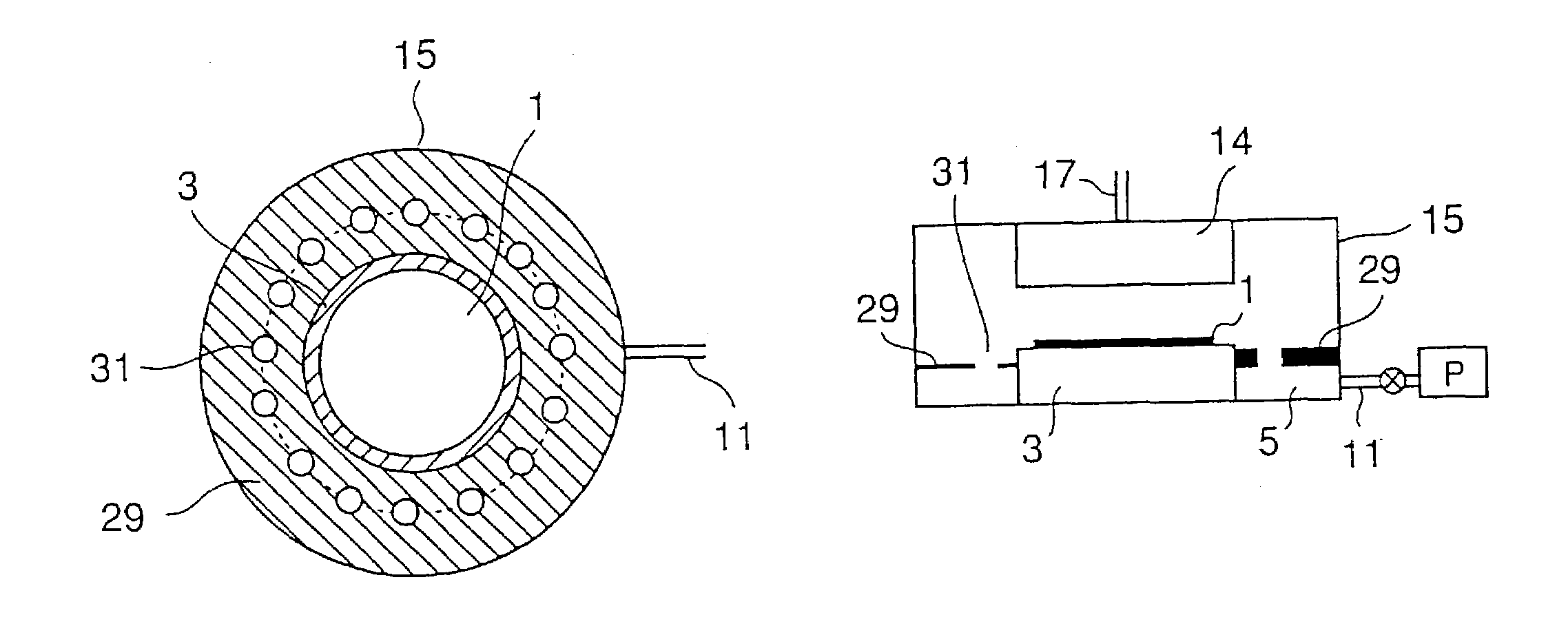
[0151]FIG. 11 shows the structure of a baffle plate 29 of the third embodiment of the present invention. FIG. 12 shows the structure of a gas process chamber on which the baffle plate 29 of this embodiment is mounted. As shown in FIG. 12, the baffle plate 29 has a greater thickness in the vicinity of the connecting port of the exhaust pipe 11 so as to restrict an increase in exhaust flow rate per hole due to an excessive differential suction pressure, thereby reducing a conductance by the gas flow. At the upstream side of the gas flow, where the differential suction pressure decreases, the ba...


PUM

PropertyMeasurementUnit
diameteraaaaaaaaaa
pressureaaaaaaaaaa
pressureaaaaaaaaaa

Abstract

The present invention provides a gas process apparatus that realizes uniform exhaust without depending on process conditions, a gas process chamber that constitutes the gas process apparatus, a baffle plate mounted on the gas process chamber, a method of producing the baffle plate, and an apparatus for producing the baffle plate. The baffle plate of the present invention serves as a partition between a process space in which a chemical process is carried out with a supplied gas, and a duct that is adjacent to the process space and functions to discharge exhaust gas generated as a result of the chemical process. In accordance with the difference between the pressures on both sides of the baffle plate, which difference varies depending on the location on the baffle plate, the baffle holes are disposed on a plurality of locations on the baffle plate.

Description

[0001]This application is the National Phase of International Application PCT / JP00 / 09106, which was filed in the English language on Dec. 21, 2000 and designated the U.S., which in turn claims priority to Japanese application No. 11-368473, filed Dec. 24, 1999, both of which are incorporated herein in their entirety by reference.TECHNICAL FIELD[0002]The present invention relates to a gas processing apparatus that discharges exhaust gas generated as a result of chemical processing, to a baffle plate incorporated into the gas processing apparatus, and a method of and apparatus for producing the baffle plate.BACKGROUND ART[0003]FIG. 1 shows the structure of an apparatus that performs single wafer processing in a hermetically sealed chamber used in a wafer preprocessing step of semiconductor production. As shown in FIG. 1, the processing apparatus comprises: a wafer placing stand 3 on which a wafer 1, a glass substrate, and other electronic material substrates are placed; an exhaust duc...

Claims


Application Information

Patent Timeline
Patent Type & Authority Patents(United States)
IPC IPC(8): H01L21/3065C23C16/00C23C16/455H01L21/306B01J19/00H01L21/302C23C16/44H01J37/32H01L21/205
CPCC23C16/4412C23C16/45591H01J37/3244H01J37/32449H01J37/32834B01J2219/00777H01L21/00
Inventor KOMIYA, TAROOSADA, HATSUOHOSAKA, SHIGETOSHIYONENAGA, TOMIHIROTOMOYASU, MASAYUKI
Owner TOKYO ELECTRON LTD
Why Eureka
Try Eureka