Apparatus and method for stabilization or oxidation of polymeric materials

a polymer material and apparatus technology, applied in the field of apparatus and methods for stabilizing or oxidizing polymeric materials, can solve the problems of limiting the rate of oxidation, requiring more space, and limiting the carbonization and graphitization of materials,

Active Publication Date: 2010-01-19
4X INTPROP HLDG LLC +2
View PDF26 Cites 27 Cited by
  • Summary
  • Abstract
  • Description
  • Claims
  • Application Information

AI Technical Summary

Problems solved by technology

Traditionally, the first oxidation or stabilization processing step is the most time-consuming and rate-limiting step in conventional carbon fiber manufacturing, and it requires more space than all other steps combined.
That work was independent of precursor material, but is limited to the carbonization and graphitization of materials that already have bee

Method used


Image

  • Apparatus and method for stabilization or oxidation of polymeric materials
  • Apparatus and method for stabilization or oxidation of polymeric materials
  • Apparatus and method for stabilization or oxidation of polymeric materials

Examples


example 1

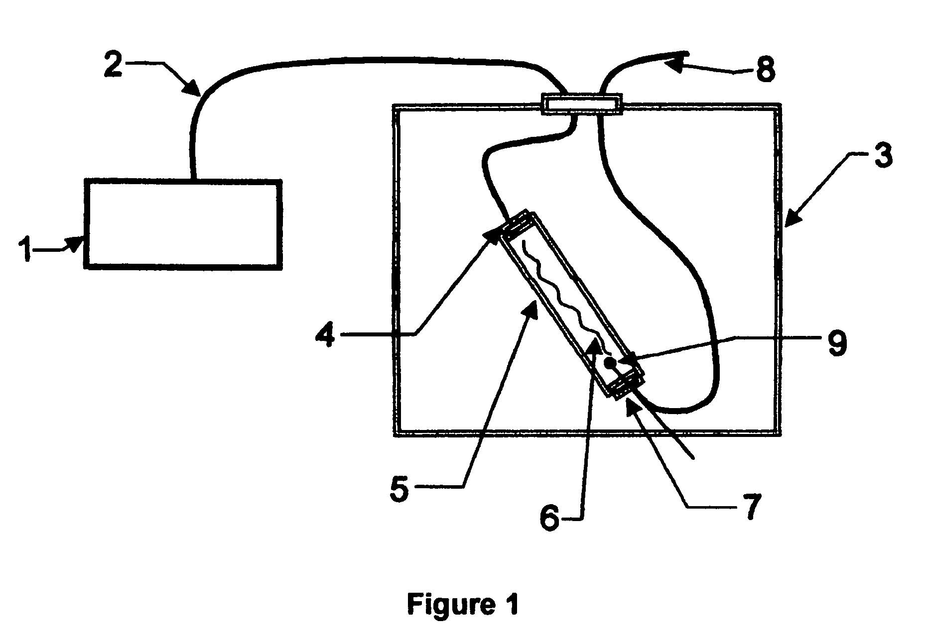
[0034]As shown schematically in FIG. 1, a commercial ozone generator 1 (Model AX8200, ASTeX Products, 90 Industrial Way, Wilmington, Mass. 01887) was connected via a PTFE tube 2 into a mechanically programmable oven 3 (Model DKN400, Yamato Scientific America, 925 Walsh Ave., Santa Clara, Calif. 95050) through a silicone rubber inlet stopper 4, and into a 1.25″ I.D.×14″ long quartz tube 5 containing the PAN precursor 6. Exhaust from the quartz tube passed out through exit stopper 7 and into another PTFE tube 8 for disposal. In addition to the set temperature control of the oven 3, three different thermocouples were inserted, one into the oven volume, another at the interior inlet of the quartz tube, and one (shown at 9) at the interior exit end of the quartz tube. During initial testing, the ozone-containing process gas at 6 slpm initially entered the oven at room temperature and became heated as it passed into the quartz tube and over the fibers. This gas contained no more than 10% ...

example 2

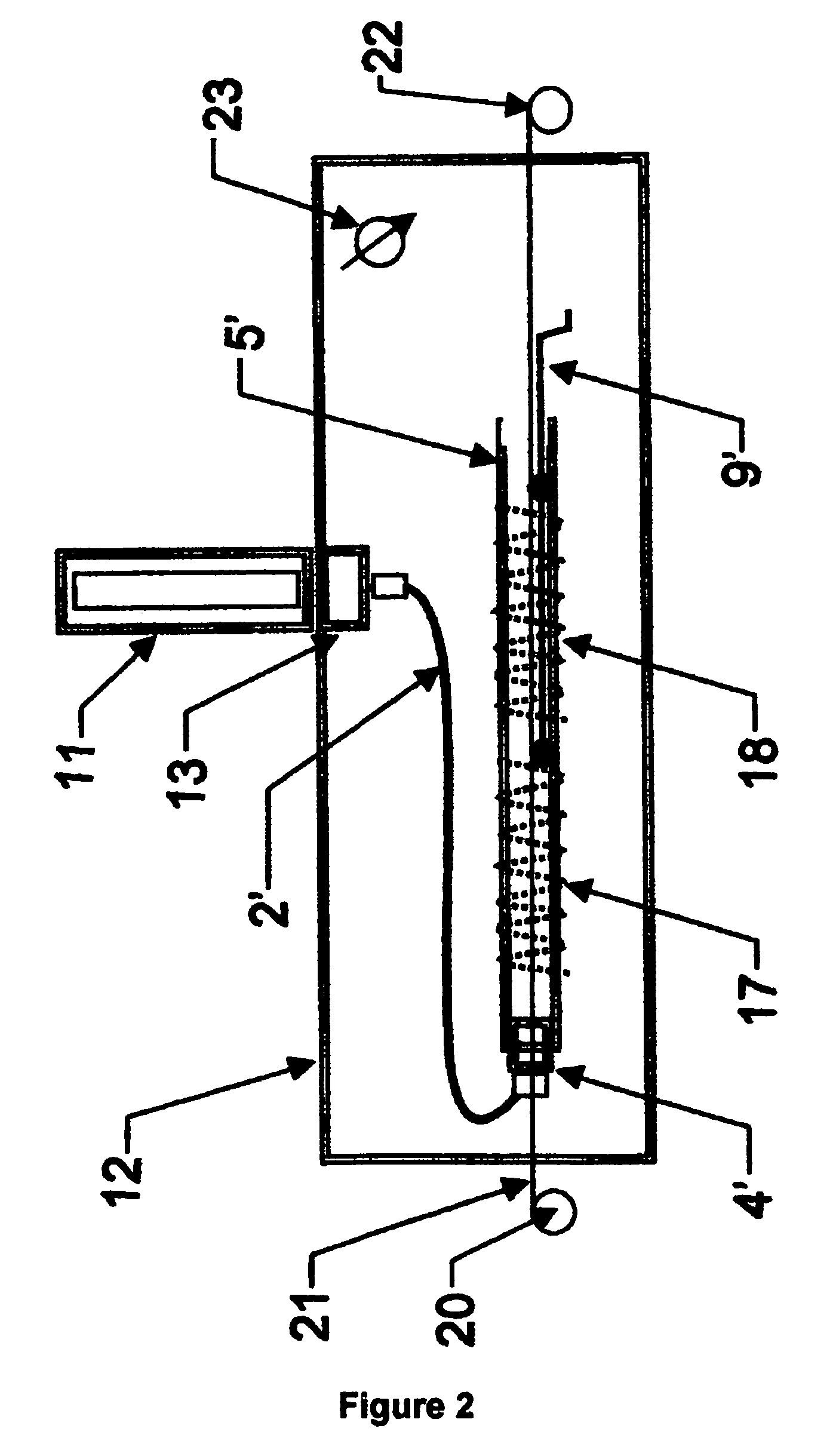
[0038]FIG. 2 shows schematically a continuous-fiber processing system. Ozone was supplied from a diffuse dielectric barrier plasma discharge device 11 which sat atop an safety enclosure chamber 12 The ozone was collected at the exit 13 of the plasma device 11 and transferred via a PTFE hose 2′ to the inlet 4′ of a quartz tube 5′ that had two separately heated sections 17, 18. Each heated section was about 10″ long and consisted of heater wire wound externally around the quartz tube and was equipped with a thermocouple 9′ to monitor the internal temperature. Supplied from a reel 20 the precursor tow 21 consisting of 3k filaments was fed through the heated tube to a take-up reel 22 The interior of the enclosure was maintained at slightly negative pressure via an exhaust port 23. Results of several runs using this setup are summarized in Table 2.

[0039]

TABLE 2Densification of Moving PAN Tow in Heated OzoneTemp., ° C.StartingTreatedRemnantTreatmentInlet / % O2 / density,density,Heat,time, mi...

example 3

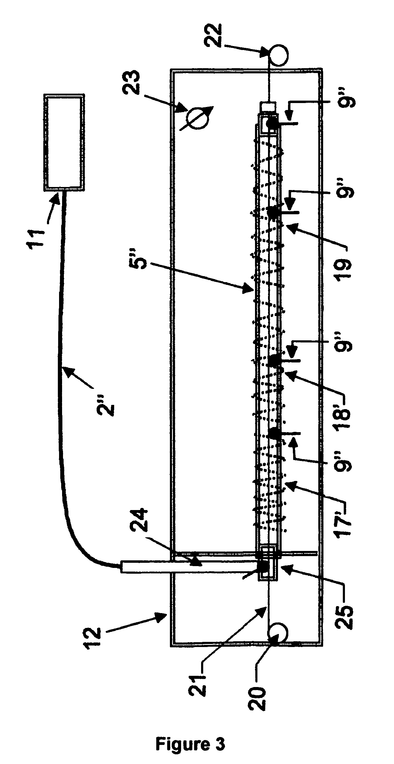
[0042]FIG. 3 shows another embodiment of the present invention that is configured to have additional heaters and a generally longer processing chamber so that the fibers would have a greater residence time for a given line speed. This allows the fiber to proceed through a more gradual temperature gradient and to be processed at a higher line speed. In excess of 100 experiments were performed using this embodiment of the inventive device. Ozone was supplied from a difuse dielectric barrier plasma discharge device 11, which is situated separately from the fiber processing unit that is enclosed in a safety enclosure chamber 12. The ozone was transferred via ˜25′ PTFE hose 2″ to an inlet preheater 24 which was connected to one side of a tee 25. The other side of the tee was connected to a quartz tube 5″ that had three separately heated sections 17′, 18′, 19. Each heated section (5″, 9″, and 11″ long, respectively) consisted of heater wire wound externally around the quartz tube 5″ and e...


PUM

PropertyMeasurementUnit
Temperatureaaaaaaaaaa

Abstract

An apparatus for treating polymeric materials comprises a treatment chamber adapted to maintain a selected atmosphere at a selected temperature; a means for supporting the polymeric material within the chamber; and, a source of ozone-containing gas, which decomposes at the selected temperature yielding at least one reactive oxidative species whereby the polymer is stabilized and cross linked through exposure to the oxidative species in the chamber at the selected temperature. The ozone may be generated by a plasma discharge or by various chemical processes. The apparatus may be configured for either batch-type or continuous-type processing. The apparatus and method are especially useful for preparing polymer fibers, particularly PAN fibers, for later carbonization treatments as well as to make flame-retardant fabrics.

Description

CROSS-REFERENCE TO RELATED APPLICATION[0001]This application is a Continuation-in-Part of Applicants' U.S. patent application Ser. No. 11 / 344,573 filed on Jan. 31, 2006, now U.S. Pat. No. 7,534,854 which in turn claims the benefit of Provisional Patent Application Ser. No. 60 / 666,301 filed by the present inventors on Mar. 29, 2005, the entire disclosure of which is incorporated herein by reference.STATEMENT REGARDING FEDERALLY SPONSORED RESEARCH[0002]This invention was made with Government support under Contract No. DE-AC05-000R22725 awarded by the U.S. Department of Energy to UT-Battelle, LLC, and the Government has certain rights in this invention.BACKGROUND OF THE INVENTION[0003]1. Field of the Invention[0004]The invention pertains to apparatus and methods to treat polymeric materials, and more particularly to systems and methods for chemically-assisted oxidation and stabilization of thermoplastic materials in preparation for high-temperature carbonization or for other uses.[0005...

Claims


Application Information

Patent Timeline
IPC IPC(8): C08G63/02B32B27/06
CPCB29C59/14C01B13/10D06M10/06D06M11/34C08J7/12D01F9/328B29C2059/145B29K2033/20Y10T428/2904
Inventor PAULAUSKAS, FELIX L.SHERMAN, DANIEL M.
Owner 4X INTPROP HLDG LLC
Why Eureka
Try Eureka