Tool string direct electrical connection

Inactive Publication Date: 2010-01-19
SCHLUMBERGER TECH CORP
View PDF77 Cites 28 Cited by
  • Summary
  • Abstract
  • Description
  • Claims
  • Application Information

AI Technical Summary

Problems solved by technology

Optimally, a system for transmitting electricity between surface equipment and downhole tools in a tool string should be transparent to the tool string operator or crew, as time delays introduced by a complicated telemetry system may represent a significant amount of money.

Method used


Image

  • Tool string direct electrical connection
  • Tool string direct electrical connection
  • Tool string direct electrical connection

Examples


Embodiment Construction

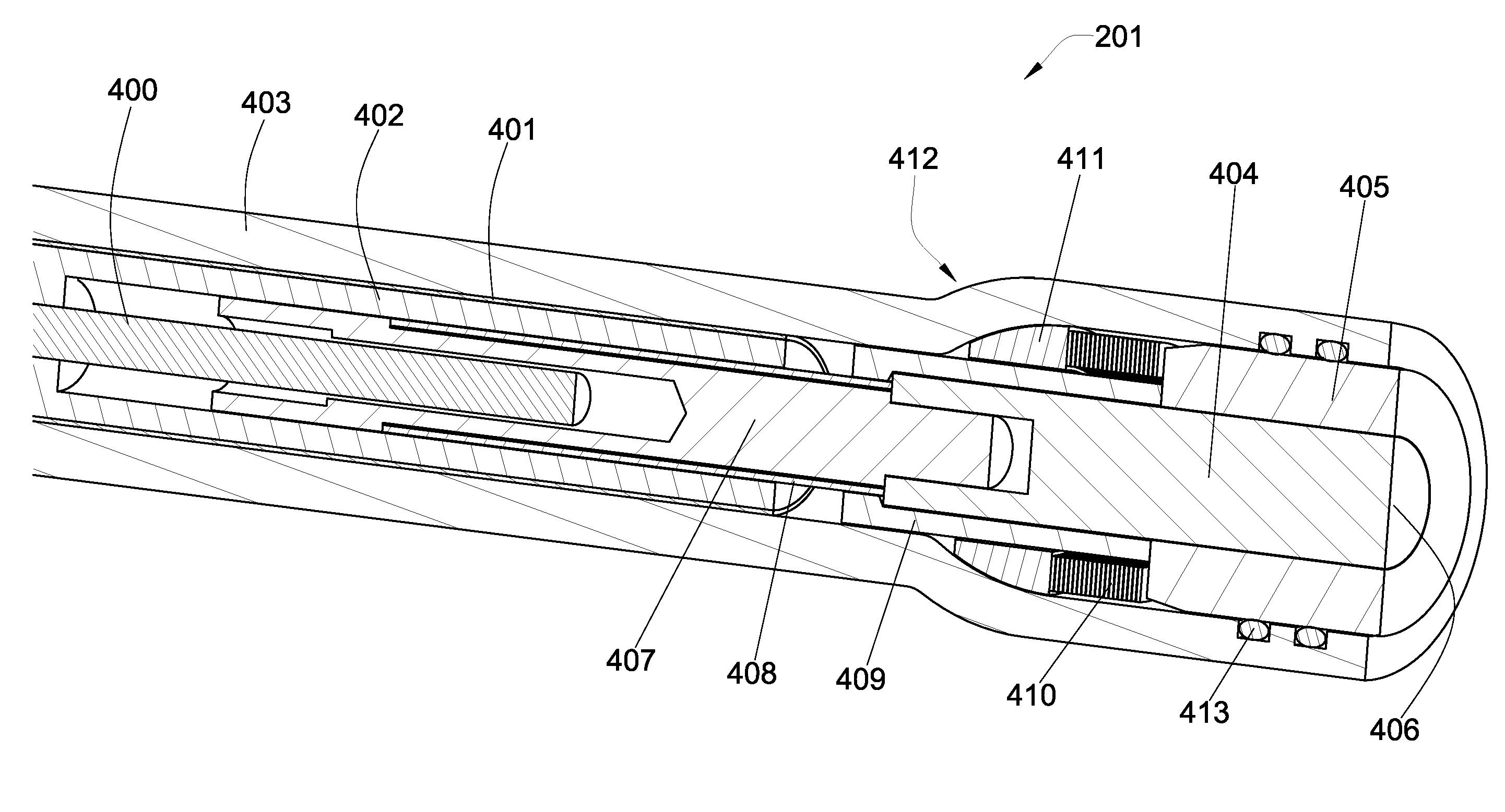
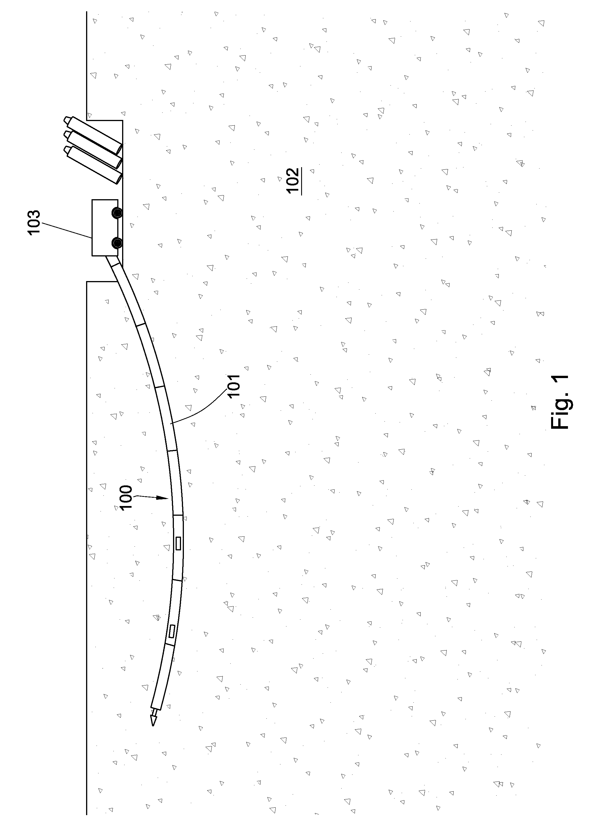
[0028]A drill string 100 may drill a bore hole 101 in subterranean formation 102 in a horizontal direction. In the embodiment of FIG. 1, a rig 103 is placed at the surface and is angled such that the drill string 100 penetrates the surface at a non-perpendicular angle. As the drill string 100 advances, the bore hole 101 gradually becomes generally parallel to the surface and then eventually returns to the surface at a predetermined location, at which time a back reamer may be attached to the drill string 100 and pulled back through the bore hole 101 in order to widen the hole for pipe and other tools to be inserted. Cables such as fiber optic or metal cables may also be attached to the drill string 100 as it is pulled back through the bore hole 101.

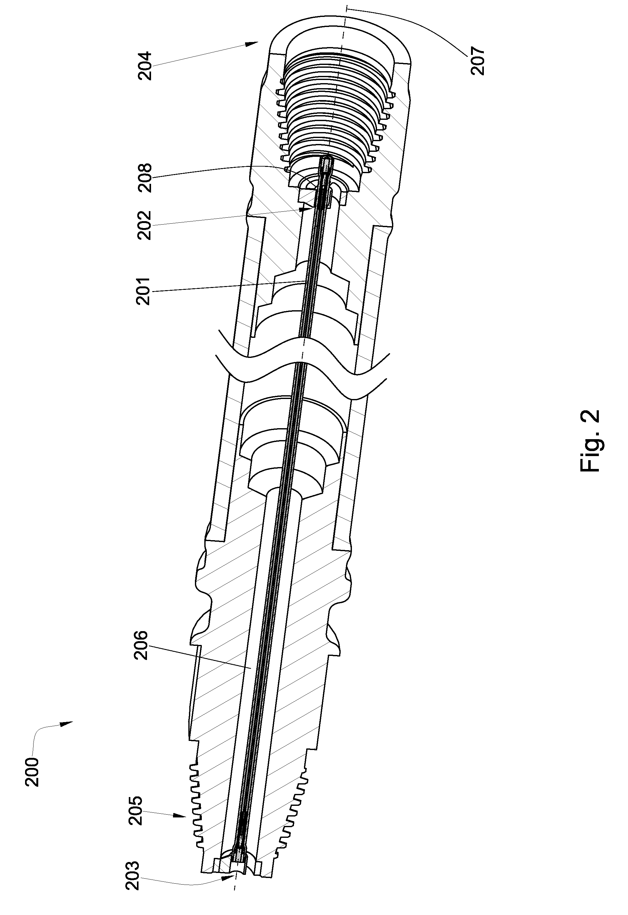
[0029]To accomplish horizontal directional drilling, the drill string 100 may comprise a steering mechanism. The steering mechanism may allow the drill string 100 to change direction while drilling, which may allow the drill string 100 to...


PUM


Abstract

A downhole electrical transmission system having first and second tubular bodies coupled together by mating threads, each tubular body having a bore. An electrical conductor assembly is disposed within the bore of each tubular body. At least one end of each assembly has an electrical contact surrounded by a dielectric material, the electrical contact and dielectric material forming a polished, planar mating surface. The mating surfaces span an entire cross section of the end and are perpendicular to a central axis of the tubular bodies. The mating surfaces of each electrical conductor assembly are substantially engaged at a compressive load when the tubular bodies are fully mated.

Description

BACKGROUND OF THE INVENTION[0001]The present invention relates to the field of data and / or power transmission. More specifically, it relates to the field of apparatus for transmitting data and / or power through such downhole tool strings.[0002]Downhole tool strings have become increasingly versatile in the last half century. In addition to traditional oil, gas, and geothermic exploration and production purposes, tubular tool strings are often used for what is known as horizontal directional drilling to install underground power lines, communication lines, water lines, sewer lines, and gas lines. This sort of downhole drilling is particularly useful for boring underneath roadways, waterways, populated areas, and environmentally protected areas.[0003]The increased versatility of downhole drilling with tool strings has led to a higher demand for apparatus that are able to transmit a power signal to downhole equipment as well as transmit data between downhole and surface tools. Hence, se...

Claims


Application Information

Patent Timeline
Patent Type & Authority Patents(United States)
IPC IPC(8): G01V3/00
CPCE21B17/028H04B2203/5475E21B17/0285
Inventor HALLDAHLGREN, SCOTT
Owner SCHLUMBERGER TECH CORP
Why Eureka
Try Eureka