Radio receiver and noise estimated value correction method

a technology of noise estimated value and receiver, which is applied in the field of radio receiver, can solve the problems of large degradation of characteristics and equalization characteristics

Inactive Publication Date: 2010-01-19
NEC CORP
View PDF7 Cites 6 Cited by
  • Summary
  • Abstract
  • Description
  • Claims
  • Application Information

AI Technical Summary

Benefits of technology

[0012]The present invention has been made to solve the above-described problem, and has as its object to provide a radio receiver and noise estimated value correction method capable of correcting degradation in a noise estimated value under a fading environment.

Problems solved by technology

Hence, when a radio device with a high transmission rate moves at a high speed, fading occurs, resulting in a large degradation in the characteristics.
For example, in a radio receiver including an MMSE equalizer, since a weight value obtained by using a noise estimated value and a channel estimated value is incorrect, the equalization characteristic degrades.

Method used


Image

  • Radio receiver and noise estimated value correction method
  • Radio receiver and noise estimated value correction method
  • Radio receiver and noise estimated value correction method

Examples


first embodiment

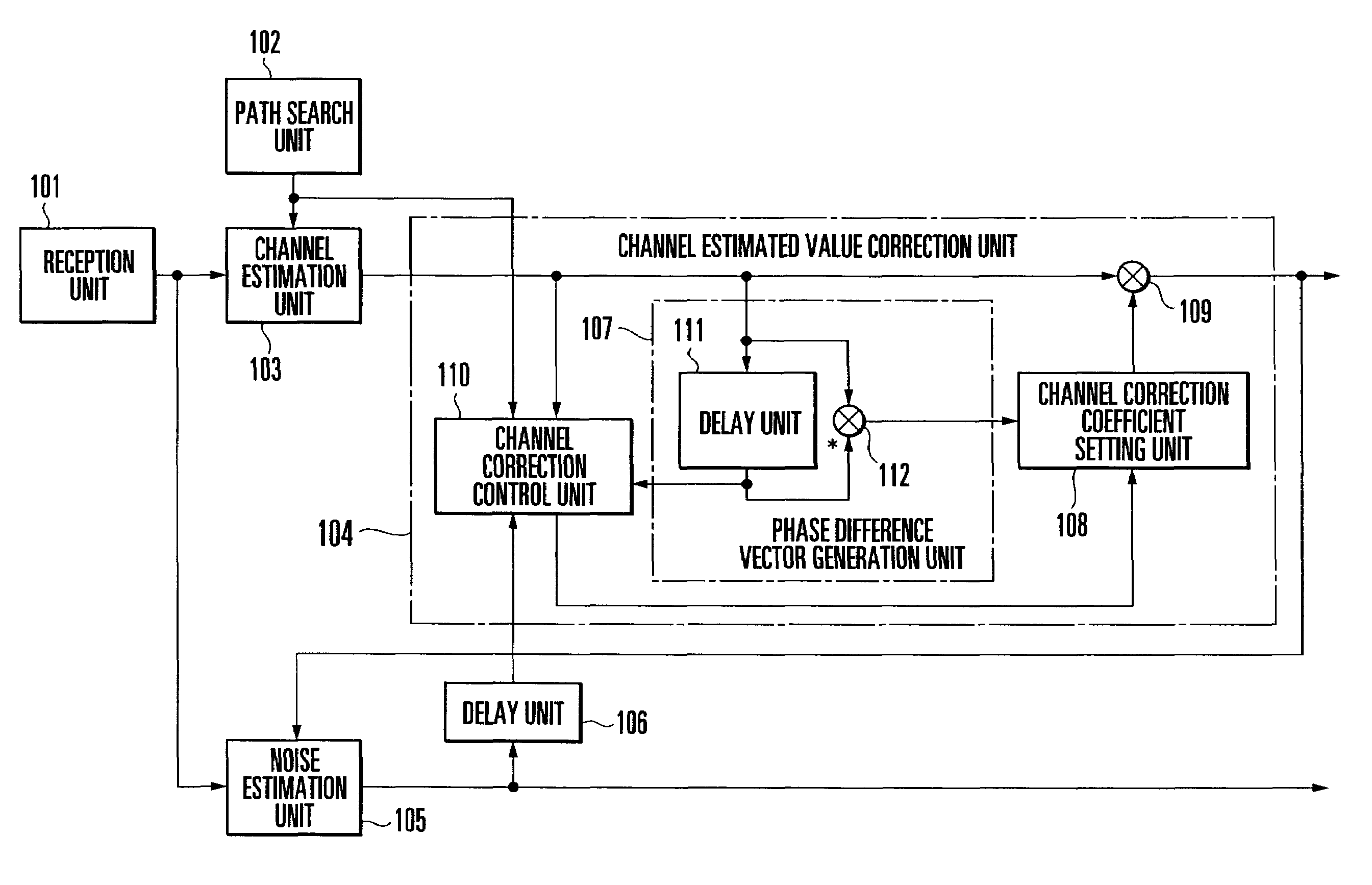
[0029]As shown in FIG. 1, the channel estimated value correction apparatus and noise estimated value correction apparatus of a radio receiver according to the first embodiment of the present invention comprise a channel estimation unit 103 which obtains a channel estimated value from a received signal at a predetermined period by using a known pilot signal, a channel estimated value correction unit 104 which corrects the channel estimated value by multiplying it by a channel correction coefficient and outputs the corrected channel estimated value, a noise estimation unit 105 which obtains a corrected noise estimated value by correcting a noise estimated value on the basis of the received signal and the corrected channel estimated value, and a delay unit 106 which delays the corrected noise estimated value from the noise estimation unit 105 by a time corresponding to a predetermined period.

[0030]The channel estimated value correction unit 104 comprises a phase difference vector gener...

second embodiment

[0045]The second embodiment of the present invention will be described next.

[0046]As shown in FIG. 5, the noise estimated value correction apparatus of a radio receiver according to the second embodiment of the present invention comprises a channel estimation unit 203 which obtains a channel estimated value from a received signal at a predetermined period by using a known pilot signal, a noise correction coefficient calculation unit 204 which obtains a noise correction coefficient from the channel estimated value, and a noise estimation unit 205 which obtains a corrected noise estimated value by correcting a noise estimated value on the basis of the received signal, channel estimated value, and noise correction coefficient.

[0047]The noise correction coefficient calculation unit 204 comprises a phase difference vector generation unit 206 which outputs a phase difference vector as the product of the complex conjugate of the preceding channel estimated value and the current channel est...

third embodiment

[0059]The third embodiment of the present invention will be described next. This embodiment shows a detailed example in which the channel estimated value correction apparatus and noise estimated value correction apparatus of the first embodiment or the noise estimated value correction apparatus of the second embodiment is applied to a mobile wireless communication system of, e.g., CDMA.

[0060]A base station 301 comprises a base station network communication unit 302, base station channel encoding unit 303, base station modulation unit 304, base station spreading modulation unit 305, base station transmission unit 306, base station transmission antenna 308, base station reception antenna 332, base station reception unit 333, base station correction path search unit 338, base station correction equalization unit 335, base station demodulation unit 336, and base station channel decoding unit 337.

[0061]A mobile station 311 comprises a mobile station reception antenna 312, mobile station ...


PUM


Abstract

A radio receiver includes a channel estimation unit, phase difference vector generation unit, correction coefficient setting unit, and noise estimation unit. The channel estimation unit obtains a channel estimated value from a received signal at a predetermined period by using a known pilot signal. The phase difference vector generation unit obtains a phase difference vector between the preceding channel estimated value and the current channel estimated value. The correction coefficient setting unit sets a correction coefficient corresponding to the phase difference vector. The noise estimation unit obtains a corrected noise estimated value by correcting a noise estimated value on the basis of the received signal and the correction coefficient. A noise estimated value correction method is also disclosed.

Description

BACKGROUND OF THE INVENTION[0001]The present invention relates to a radio receiver that uses channel estimation in receiving and demodulating a signal under a fading environment and, more particularly, to a radio receiver and noise estimated value correction method of correcting a noise estimated value.[0002]In recent mobile communication, packet data traffic is becoming faster and increasing the capacity. Transportation is also speeding up simultaneously. Hence, when a radio device with a high transmission rate moves at a high speed, fading occurs, resulting in a large degradation in the characteristics.[0003]To reduce the influence of fading, reference 1 (Japanese Patent Laid-Open No. 2004-7793) proposes a demodulation apparatus which obtains a channel estimated value by assigning weights to pilot signals contained in a received signal and averaging them and demodulates the received data by using the channel estimated value in mobile wireless communication such as CDMA (Code Divis...

Claims


Application Information

Patent Timeline
Patent Type & Authority Patents(United States)
IPC IPC(8): H03D1/04H04L1/00H04B1/707H04B1/7117H04B7/005
CPCH04L25/0224H04L25/03038H04B2201/70701H04L2025/03445H04L2025/03764
Inventor MATSUMOTO, MARIKO
Owner NEC CORP
Why Eureka
Try Eureka