Method and apparatus for bundling objects

a technology for bundling objects and restraining objects, applied in the direction of bundling articles, hose connections, manufacturing tools, etc., can solve the problems of incompletely formed locking dimples, inability to fully and completely form, and inability to fully and completely lock, so as to optimize the application of force over time, improve the formation of superior locking dimples, and optimize the effect of forming a superior locking dimpl

Active Publication Date: 2010-01-26
BAND IT IDEX
View PDF130 Cites 37 Cited by
  • Summary
  • Abstract
  • Description
  • Claims
  • Application Information

AI Technical Summary

Benefits of technology

[0012]The present invention overcomes these problems and provides an improved band clamp and tooling for locking a band clamp. In one embodiment, the apparatus or tool used to deform and lock the band relative to the buckle comprises a movable punch and knife. The profile of the knife-edge, compared to that of the prior art, is improved and causes the application of the dimple forming and cutting force to vary over time. To optimize the formation of a superior locking dimple, it is important to optimize the application of force over time. The varied application of force over time creates an improved locking dimple by initially applying only a portion of the driving force to cut the band. Rather than instantaneously cut the entire band width, the profile of the knife-edge causes a gradual cutting of the band. Also, the profile of the knife-edge may be designed to allow the punch to dwell inside the locking dimple for a longer period of time during the forming process. This causes more material to be moved as part of the cold forming process and reduces spring back of the metal, creating a more fully formed locking dimple. In the preferred embodiment, as shown in FIGS. 1-4, the knife-edge has multiple non-collinear portions and the cutting starts at the center of the band and moves across the width of the band to the lateral edges. Because the entire band width is not cut at the same time, the knife must travel a greater distance to fully cut or sever the band. This additional movement causes the punch to travel further into the band and causes the locking dimple to be more fully and completely formed. A locking dimple that is fully formed with a preferred or optimum shape performs better as a lock. Also, because the knife-edge does not simultaneously cut the entire width of the band, a smaller portion of the driving force is applied over time for cutting the band. This allows a portion of the overall driving force to be applied to forming the locking dimple.
[0013]In the preferred embodiment, the knife-edge used to cut and remove the excess portion of the free end of band is not a straight edge. Rather, there are three distinct portions or sections to the knife-edge, for example as shown in FIG. 1. The three edge sections are coplanar, but not collinear. The center section of the knife-edge is parallel to the surface of the band. It forms the leading edge of the knife-edge and impacts the band first. The knife-edge of the preferred embodiment also comprises two lateral portions that extend in opposite directions from the center portion. The lateral knife-edge portions are angled upwardly, relative to the surface of the band, to create an overall tapered or angled edge as shown in FIG. 2. Thus, the entire base of the knife body does not engage the band at one time, as is the case of the prior art knife body shown in FIG. 5, and the knife edge does not engage the entire width of the band simultaneously. Rather, the knife-edge gradually cuts the band outwardly from the center. As a result, more of the downward force can be applied to driving the punch into the band, allowing the punch to dwell, and fully forming the locking dimple. If the free end of the band is cut too quickly, the locking dimple will not form fully and completely. An incompletely formed locking dimple is more susceptible to allowing slip-back and is also susceptible to failure. In addition, the base of the knife is also tapered as shown in FIG. 3. The base or lower portion of the knife body tapers away from the knife-edge and accommodates rotation of the tool and the knife body during tensioning of the band prior to cutting.
[0015]Additionally, the shape of the punch tip is improved. In one embodiment, shown in FIGS. 9 and 10, the punch tip is generally hemispherical in shape. This shape forms at least a portion of the side walls of the locking dimple in the shape of a cylinder. It further contributes to making the side walls generally uniformly thick, compared to the prior art design. It also forms at least a portion of the side walls generally parallel to the inside surface of the apertures formed in the band and bottom of the buckle, rather than a wall that is sloped relative to the inside surfaces of these apertures such as in the prior art design. The abutting parallel walls create an improved locking force. As a result, the generally parallel walls reduce or eliminate the slip-back caused by separation of the overlapping band portions, Δz, inside the buckle. Nonetheless, should the upper band separate from the lower portion of the band within the interior of the buckle, the fact that the locking dimple is more fully, uniformly and deeply formed, and the fact that at least an abutting portion of the outer wall of the locking dimple is substantially parallel to the inside surface of the aperture formed in the band, will cause the locking dimple to maintain a locked relationship of the band clamp beyond that provided by the prior art band clamp. In addition, by switching to a punch tip where the leading portion is rounded, the cold working of the band to form the locking dimple does not thin the walls of the locking dimple to the same extent as the conical shaped punch tip. As a result, the chances of a failure from shearing the locking dimple or dimple collapse is substantially reduced.
[0017]In one embodiment, the apparatus and method of the present invention also forms the locking dimple at a position closely adjacent the inner surface of the aperture in the band (FIG. 24). This is accomplished by driving the punch into the band at an angle relative to the inner surface of the aperture formed in the underlying band. By doing so, a substantial portion of the slip-back, Δx, in the band is substantially reduced or completely eliminated. The ability to position the punch at an angle relative to the overlapping band portions may be further facilitated by angling the base portion of the knife body so that it does not contact the band all at once, and altering the travel of the knife body to reciprocate at an angle relative to the overlapping band portions.
[0019]By altering the knife-edge profile an improved locking dimple is formed. The formation of an improved locking dimple improves retained tensile force by reducing losses attributed to slip back of the band and failure of the locking dimple. By improving retained tensile force, a given band can accommodate a greater tensile load, achieving a greater loop tensile strength, without needing to be subjected to a greater clamping force applied at the time of locking and band cut off. The preferred embodiment of the present invention provides an increase of approximately sixty-seven percent in the ratio of lock strength to ultimate band strength, the ratio of lock strength to cross-sectional area of the band and in the ratio of lock strength to band yield strength, regardless of the physical dimension or properties of the band. Nevertheless, it will be appreciated by those of ordinary skill in the art that a ten percent increase in these normalized characteristics represents a substantive improvement over existing ties as it presents an order of magnitude improvement. Thus, a ten percent improvement is within the scope of the invention and can be obtained by practicing the principles embodied herein in a less precise or controlled manner.

Problems solved by technology

If the free end of the band is cut too quickly, the locking dimple will not form fully and completely.
An incompletely formed locking dimple is more susceptible to allowing slip-back and is also susceptible to failure.

Method used


Image

  • Method and apparatus for bundling objects
  • Method and apparatus for bundling objects
  • Method and apparatus for bundling objects

Examples


Embodiment Construction

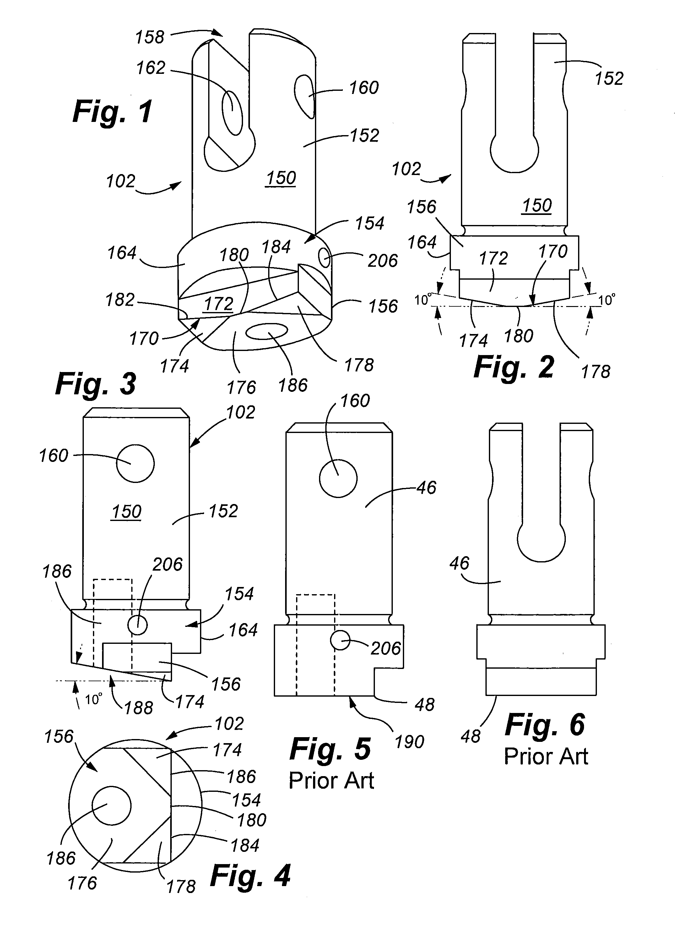
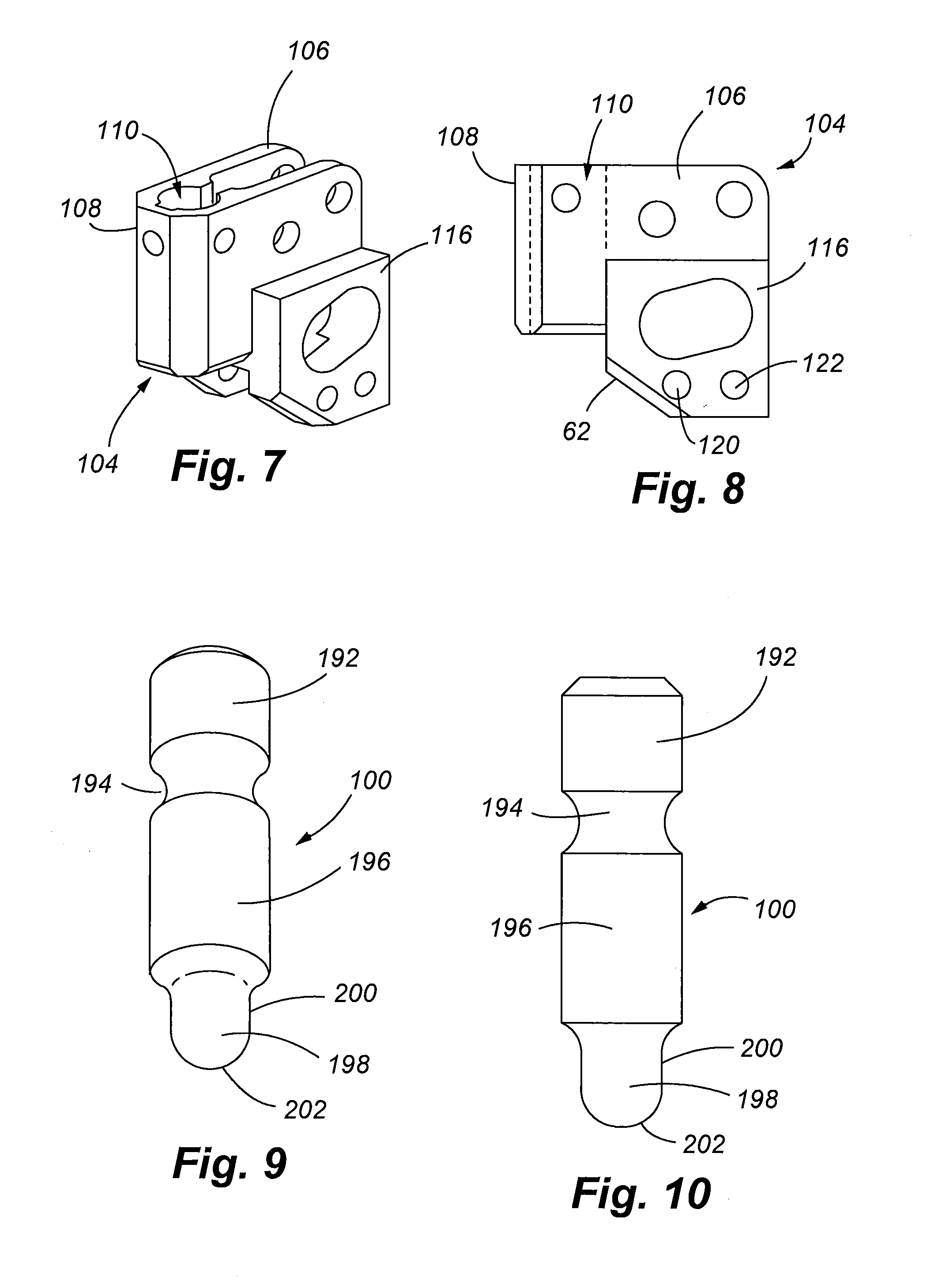
[0058]Referring to FIGS. 1 and 9, one embodiment of an improved punch and knife for use in a banding system, such as the Band-It ⅜″ Tie-Lok® system manufactured and sold by the Assignee of the present invention, is shown. In use, both the punch 100 and the knife 102 are positioned in a tool head 104. The tool head 104, shown in FIGS. 8 and 9, is stationary and the knife and punch move along a linear path between an upper position and a lower position. The tool head 104 comprises a body 106 having a first portion 108 with a cylindrical shaft or bore 110 for holding the knife 102 and guiding its reciprocating movement. The tool head has a second portion 116 in which a stationary cutter blade 118 is secured. The second body portion 116 includes a pair of apertures 120, 122 through which pins 124, 126 are positioned to secure the cutter blade 118. The cutter blade 118 includes a bore 128 to receive one of the pins.

[0059]A preferred embodiment of the cutter blade 118 is shown in FIGS. 11...


PUM

PropertyMeasurementUnit
angleaaaaaaaaaa
angleaaaaaaaaaa
distanceaaaaaaaaaa

Abstract

An improved tool for locking a band clamp, and an improved lock for a band clamp is disclosed. The tool includes a knife body having a knife edge that progressively cuts the free end of the band over a period of time, rather than simultaneously cutting the entire band width. In one embodiment, this is accomplished with a knife edge that is non-linear. The tool further includes a punch with a rounded or hemispherical shaped leading tip that forms an improved locking dimple. The locking dimple forms an improved lock having side walls that are, at least in part, parallel with the walls of the surrounding aperture in the band. By varying the profile of the knife edge, the punch can more fully form an improved locking dimple.

Description

FIELD OF THE INVENTION[0001]The present invention relates to a method and apparatus for bundling and restraining objects, such as tubing or electrical wires, into a single bundle or for securing covering material or sheeting around objects. In general, the invention relates to securing or locking a band and a buckle of a band clamp. More particularly, the invention relates to an improved lock between the band and a buckle, as well as the method and apparatus for forming the improved lock.BACKGROUND OF THE INVENTION[0002]Flat band and buckle assemblies, also known as ties, have existed for sometime for use in bundling or securing objects together. Typically, a tie, comprising an elongate band having a free end and a buckle at the opposite end, is wrapped around a group of objects with the free end passed through the buckle. The buckle and overlapping band are secured in some fashion to thereby constrain the group of objects. Similarly, tools for tightening bands around objects, for s...

Claims


Application Information

Patent Timeline
Patent Type & Authority Patents(United States)
IPC IPC(8): B21D39/00F16L33/00
CPCB65B13/027B65B13/345B65D63/08Y10T24/1457Y10T29/49936
Inventor STILLINGS, MATTHEW J.NELSON, DANIEL J.MARELIN, MIKLOS B.STOLTZ, RYAN M.
Owner BAND IT IDEX
Why Eureka
Try Eureka