Processes and apparatuses for producing porous materials

a technology of porous materials and processing equipment, applied in the direction of chemistry apparatus and processes, paper/cardboard articles, silicon compounds, etc., can solve the problems of reducing the efficiency of the entire process, lack of convenience of gasoline, lack of flexibility of electrical energy stored in batteries and capacitors, etc., to promote the formation of porosity within the substrate, reduce pore size, and optimize npsi formation

Active Publication Date: 2010-11-16
INDIANA UNIV RES & TECH CORP
View PDF1 Cites 0 Cited by
  • Summary
  • Abstract
  • Description
  • Claims
  • Application Information

AI Technical Summary

Benefits of technology

[0020]A significant advantage of this invention is the ability of relative movement between a magnetic field and substrate to subject holes within the substrate to Lorentz forces during etching to promote the formation of porosity within the substrate, and the ability to do so even if the substrate is in the form of a fine particle. The Lorentz force can be advantageously utilized to drive holes toward one or more reaction fronts at the particle surface to optimize npSi formation. An optimized process that incorporates this Lorentz force effect is believed to be capable of producing npSi having decreased pore size and increased surface area. Additionally, the Lorentz force effect may also produce npSi at an increased rate when compared to standard chemical etch processes known in the prior art.

Problems solved by technology

When compared to storage for conventional chemical fuels or electric energy sources, existing hydrogen storage technologies lack the convenience of gasoline for delivery and storage capacity (energy density per unit weight), and lack the flexibility of electrical energy stored in batteries and capacitors.
This method suffers two important drawbacks: carbon dioxide byproduct is a “greenhouse gas” that some believe contributes to global warming and is therefore environmentally undesirable; and the additional weight of the chemical molecule and the reformer reduce the efficiency of the entire process, making it less attractive from a cost and performance standpoint.
However, compressed gas cylinders are quite heavy, needing sufficient strength to withstand pressures of many thousands of pounds per square inch.
This weight is a considerable drawback for portable applications, and in any usage compressed gas cylinders must be treated with care because they represent a safety hazard.
Liquid hydrogen is remarkably dense from a specific energy point of view (kilowatts per kilogram), but requires a considerable amount of additional energy to maintain the nearly absolute zero temperatures needed to keep hydrogen in a liquid state.
Liquid hydrogen also requires a heavy mass of insulation, and these factors conspire to make cryogenic storage impractical for portable and small-scale applications.
Prior hydrogen chemisorption techniques have fallen short of the goals of efficiency, convenience, and low system cost for several reasons.
In some materials, such as carbon nanotubes, the efficiency of hydrogen adsorbed per unit weight of matrix is moderate, but the method of desorption requires high heat, which brings about danger of combustion.
Additionally, the present cost of carbon nanostructures is relatively high, and control over material properties can be quite difficult in high-volume manufacturing.
These factors combine to make such approaches less than sufficiently robust for many commercial applications.
These prior methods of chemisorption do not, however, provide for desorption of hydrogen from a silicon storage medium.
Further, these conventional methods of chemisorption fail to teach methods by which the storage capacity of a silicon matrix can be increased.
However when silicon is made porous, it fluoresces (emits light) under exposure to ultraviolet light.
Electrochemical methods of the type represented in FIG. 1 have not been optimized for large quantities or high surface areas, i.e., small pore sizes.
Additionally, the reaction front moves more slowly into the substrate as the aspect ratio of the pores becomes higher, limited by the transport of reactants into the pores and reaction products out of the pores.
However, while successfully used to form npSi using wafers as a starting material, it is impractical to electrochemically etch small particles.
For example, it would be extraordinarily difficult to provide for a bias across an individual particle.
The stain etch method of producing npSi is slow and, as with electrochemical etching, requires holes for the npSi reaction to proceed.
Also similar to electrochemical etch processes, known stain etch methods are not applicable to bulk manufacture of high surface area npSi on silicon particles or powders.

Method used


Image

  • Processes and apparatuses for producing porous materials
  • Processes and apparatuses for producing porous materials

Examples


Embodiment Construction

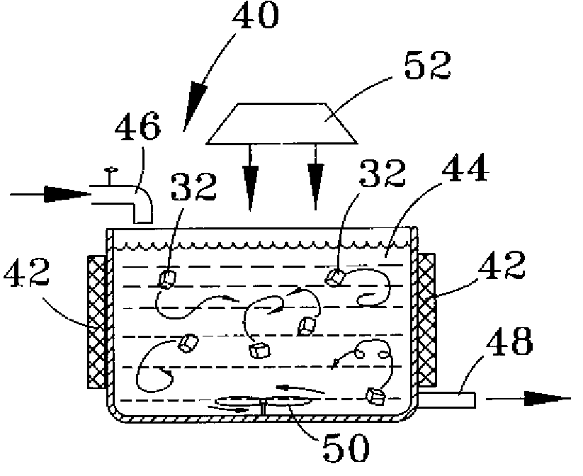
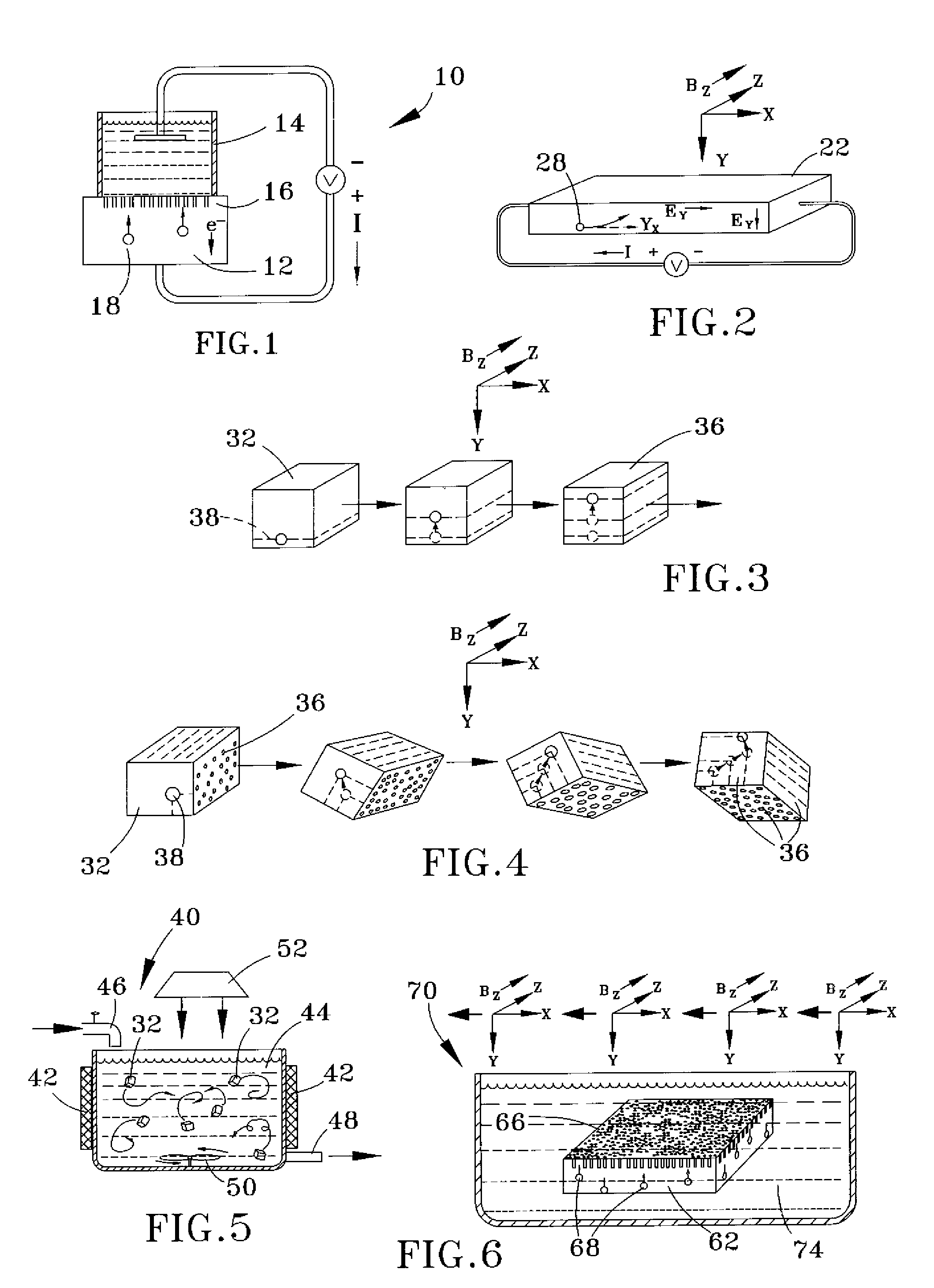
[0028]The present invention provides processes for forming a porous material, and particularly a porous solid-state hydrogen storage material, by relative movement between a magnetic field and a neutral substrate during a pore-forming etch of the substrate. The substrate contains charge carriers (electrons and positively-charged holes) that can be present in the substrate as the result of, for example, thermal generation, photogeneration, application of a very high frequency magnetic or electric field, time variation of an electromagnetic field, ionizing radiation, or appropriate doping (for example, p-doping and formation of doping gradients or p-n junctions). Because of Lorentz forces, the holes are acted upon by relative movement between the magnetic field and substrate, and thus relative movement between the magnetic field and the holes within the substrate. With the substrate properly oriented with respect to the magnetic field, holes in the substrate can be preferentially forc...


PUM

PropertyMeasurementUnit
diametersaaaaaaaaaa
wavelengthaaaaaaaaaa
temperatureaaaaaaaaaa

Abstract

Processes and apparatuses for producing a porous material, such as nano-porous silicon (npSi) media suitable for storage and retrieval of elemental hydrogen. Processes of this invention generally entail applying a magnetic field to a substrate that contains charge carriers and is in contact with an etchant, and then etching the substrate with the etchant while relative movement occurs between the substrate and the magnetic field. During etching, the charge carriers move relative to the substrate and the magnetic field, and porosity forms at surfaces of the substrate contacting the etchant.

Description

CROSS REFERENCE TO RELATED APPLICATIONS[0001]This application claims the benefit of U.S. Provisional Application No. 60 / 814,307, filed Jun. 16, 2006, the contents of which are incorporated herein by reference.STATEMENT REGARDING FEDERALLY SPONSORED RESEARCH[0002]This invention was made with United States Government support from Edison Materials and Technology Center (EMTEC), Contract No. EFC-H2-3-1C. The Government has certain rights in this invention.BACKGROUND OF THE INVENTION[0003]The present invention generally relates to processes and apparatuses used in the treatment of materials. More particularly, this invention relates to processes and apparatuses for producing porous media, such as nano-porous silicon (npSi) suitable for use in the storage and retrieval of elemental hydrogen.[0004]Hydrogen-based fuel cell technologies are being considered for a wide variety of power applications, including but not limited to mobile applications such as vehicles as an attractive alternative...

Claims


Application Information

Patent Timeline
Patent Type & Authority Patents(United States)
IPC IPC(8): B31D3/00
CPCC01B3/001C01B3/0084Y02E60/324C01B33/021Y02E60/32
Inventor CHRISTENSON, JOHN C.SCHUBERT, PETER J.
Owner INDIANA UNIV RES & TECH CORP
Why Eureka
Try Eureka