Systems and methods for improved connection to wound dressings in conjunction with reduced pressure wound treatment systems

a wound treatment system and wound dressing technology, applied in the field of wound dressing system connection and wound dressing reduction, can solve the problems of less able to successfully fight, hampered process, diminished oxygen and nutrients, etc., and achieve the effect of reducing pressure, preventing clogging, and reducing pressur

Active Publication Date: 2010-01-26
3M INNOVATIVE PROPERTIES CO
View PDF204 Cites 175 Cited by
  • Summary
  • Abstract
  • Description
  • Claims
  • Application Information

AI Technical Summary

Benefits of technology

[0014](A) A low profile reduced pressure adapter that improves the reliability of operation and prevents or reduces instances of unintentional fluid ingress into measurement lumens;
[0017](D) An improved reduced pressure adapter structure having rotational functionality to facilitate the comfort of the attachment to the patient; and
[0019]The improved reduced pressure adapter includes a conduit housing with a primary conduit and at least one secondary conduit for fluid connection to a wound dressing. The reduced pressure adapter also may include a base with a substantially circular shape. The conduit housing includes a recessed region defining an entry surface. The primary conduit connects the entry surface to a primary lumen of a multi-lumen reduced pressure delivery tube, and ancillary conduits connect the entry surface to ancillary lumens of the multi-lumen reduced pressure delivery tube. Channels positioned on the entry surface preferentially route liquids and other fluids into the primary conduit in order to prevent the clogging of the ancillary conduits, which are generally utilized to measure pressure within the wound dressing.
[0021]The improved method of measuring pressure addresses certain problems with existing pressure control in RPWT systems that result from excessive fluid incursion into the measurement lumens of the system. Each of the ancillary lumens are monitored for their responsiveness to changes in the reduced pressure source (and thus in the wound dressing itself). A slow response in one of the ancillary lumens is indicative of clogging in that lumen, and as a result, the RPWT system considers the pressure measurement from the clear ancillary lumen as the accurate measurement. The system further allows for the introduction of elevated pressure into the clogged lumen in a manner that may serve to clear the lumen of fluid obstruction, all the while the second of the two ancillary lumens may continue to function as a monitoring channel for measuring the pressure at the tissue site.
[0022]In other embodiments the improved reduced pressure adapter structure incorporates rotational functionality to improve the patient's convenience and comfort. The conduit housing is positioned on and rotatably attached to the perimeter base in a manner that allows the reduced pressure adapter and attached tubing to rotate with respect to the wound dressing thereby reducing strain on the dressing and the reduced pressure adapter.

Problems solved by technology

Unfortunately, this process is hampered when a wound is large or has become infected.
Without sufficient blood flow, the epithelial and subcutaneous tissues surrounding the wound not only receive diminished oxygen and nutrients, but are also less able to successfully fight bacterial infection and, thus, less able to naturally close the wound.
Additionally, some wounds harden and inflame to such a degree that closure by stapling or suturing is not feasible.
Generally it is not possible to characterize the pressure level at the tissue site by simply measuring the level of reduced pressure that the reduced pressure source is providing, either at the source or in the conduit lines connecting the source to the wound dressing.
Fluid flow within the primary lumen of tubing associated with RPWT systems prevents using pressure level measurements at the instrumentation from being accurate indicators of the level or stability of the pressure at the tissue site itself.
This is not always a valid assumption as, despite the fact that the measurement lumen is not forcibly drawing fluids in as is being done in the primary flow lumen of the RPWT system, it still collects fluids and other materials that inhibit or altogether block its function.
The typically smaller cross-section of such measurement lumens may reduce the port size, and therefore the chance of fluid or other matter entering the port, but the same smaller cross-section results in even minor blockages becoming significant.

Method used


Image

  • Systems and methods for improved connection to wound dressings in conjunction with reduced pressure wound treatment systems
  • Systems and methods for improved connection to wound dressings in conjunction with reduced pressure wound treatment systems
  • Systems and methods for improved connection to wound dressings in conjunction with reduced pressure wound treatment systems

Examples


Embodiment Construction

[0042]In the following detailed description of the preferred embodiments, reference is made to the accompanying drawings that form a part hereof, and in which is shown by way of illustration specific preferred embodiments in which the invention may be practiced. These embodiments are described in sufficient detail to enable those skilled in the art to practice the invention, and it is understood that other embodiments may be utilized and that logical structural, mechanical, electrical, and chemical changes may be made without departing from the spirit or scope of the invention. To avoid detail not necessary to enable those skilled in the art to practice the invention, the description may omit certain information known to those skilled in the art. The following detailed description is, therefore, not to be taken in a limiting sense, and the scope of the present invention is defined only by the appended claims.

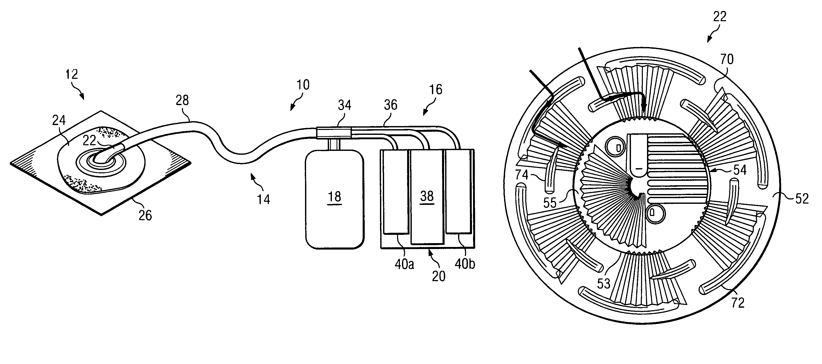
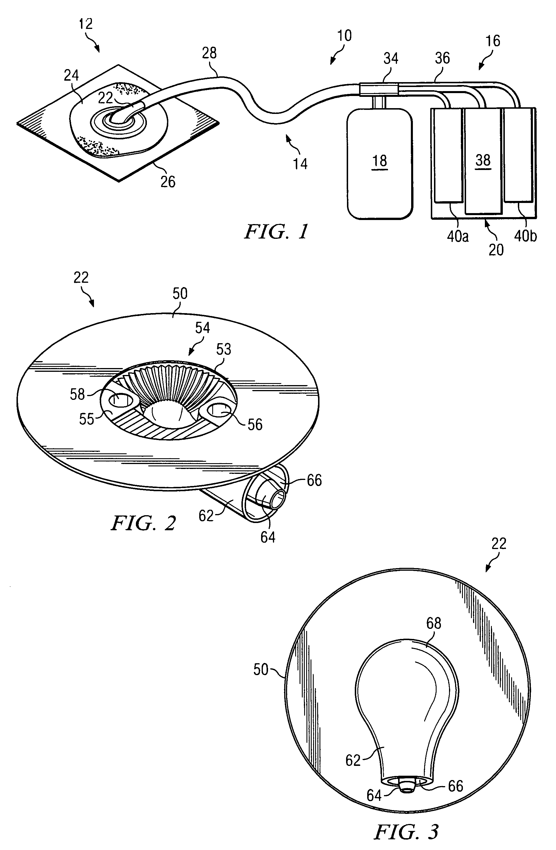
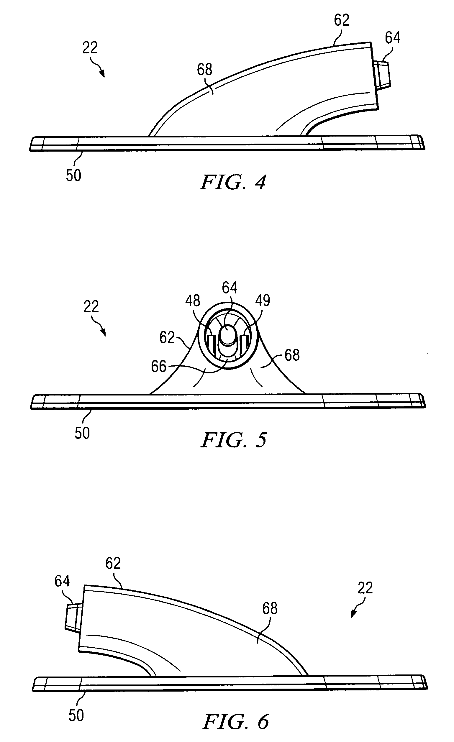
[0043]Reduced Pressure Adapter

[0044]Improvements in an RPWT system are disc...


PUM


Abstract

Described are improvements to the structure and functionality of a reduced pressure adapter used to connect a distribution manifold and a reduced pressure source instrumentation in a reduced pressure wound treatment (RPWT) system. The reduced pressure adapter reduces instances of unintentional liquid ingress into ancillary lumens of a reduced pressure delivery tube, while channeling the liquid to a primary lumen of the reduced pressure delivery tube.

Description

CROSS-REFERENCE TO RELATED APPLICATIONS[0001]This application claims the benefit of U.S. Provisional Application No. 60 / 765,548, filed Feb. 6, 2006, which is hereby incorporated by reference.BACKGROUND OF THE INVENTION[0002]1. Field of the Invention[0003]The present invention relates to generally to systems and methods for providing reduced pressure treatment to tissue, particularly open wounds. The present invention relates more specifically to systems and methods for improving the connection between a tissue dressing and reduced pressure source instrumentation used in conjunction with reduced pressure wound treatment (RPWT).[0004]2. Description of the Related Art[0005]Various therapies have been developed over time to facilitate the process of wound closure and healing. Wound closure generally involves the inward migration of epithelial and subcutaneous tissue adjacent the wound. This migration is ordinarily assisted by the inflammatory process, whereby blood flow is increased and...

Claims


Application Information

Patent Timeline
Patent Type & Authority Patents(United States)
IPC IPC(8): A61M1/00A61F13/00
CPCA61M1/0088A61M1/0031A61M1/0086A61M1/0035A61M1/0025A61M2205/3344A61M2205/584A61F13/00068A61M1/75A61M1/74A61M1/964A61M1/96A61M1/912A61M1/966A61M1/915A61M1/95A61M1/00A61M31/00A61F13/00A61M1/743A61M1/73
Inventor HEATON, KEITH PATRICKROBINSON, TIMOTHY MARKLOCKE, CHRISTOPHER BRIAN
Owner 3M INNOVATIVE PROPERTIES CO
Why Eureka
Try Eureka