
Transducer with shield

a transducer and shield technology, applied in the field of high intensity focused ultrasound transducers, can solve the problems of health risk to patients, loss of proper focus of ultrasound energy, attenuation and thermal build-up

Inactive Publication Date: 2010-01-26
LIPOSONIX
View PDF10 Cites 62 Cited by
  • Summary
  • Abstract
  • Description
  • Claims
  • Application Information

AI Technical Summary

Benefits of technology

"The present invention provides a high intensity focused ultrasound (HIFU) transducer with a shield that can protect the transducer from mechanical damage during use. The shield does not interfere with ultrasound energy transmission and can be easily replaced if needed. The transducer has a non-driven region on the front face that acts as a shield against damage. Additionally, the transducer has an aperture that extends from the front face to the back side of the transducer, which can be filled. These technical effects improve the performance and reliability of the HIFU system."

Problems solved by technology

Damage to the face of the transducer produces a number of undesirable side effects, including delamination of the matching layer from the piezoelectric ceramic, erosion of metallization on the piezoelectric material, loss of proper focus of ultrasound energy (which leads to attenuation and thermal build-up in areas that may pose a health risk to a patient), and physical destruction of the piezoelectric material used to make the transducer.
Various attempts to solve this problem have thus far proved to be unsatisfactory.
Damage may come from accidental contact of the transducer face with foreign objects, or from mechanical effects of HIFU reflections in the medium used to couple the transducer to a target surface.
One disadvantage of this solution is that the lens also acts as a boundary layer between the transducer “stack” (piezoelectric material plus any matching layers and backing) and the target tissue.
Ultrasound energy is lost through attenuation in the lens.
Reflection and refraction of ultrasound energy are also problems which must be dealt with.
As power and intensity increase in a HIFU transducer, the associated difficulties accompanying the use of a lens can become too great to overcome.

Method used


Image

  • Transducer with shield
  • Transducer with shield
  • Transducer with shield

Examples


example i

Electrical Isolation

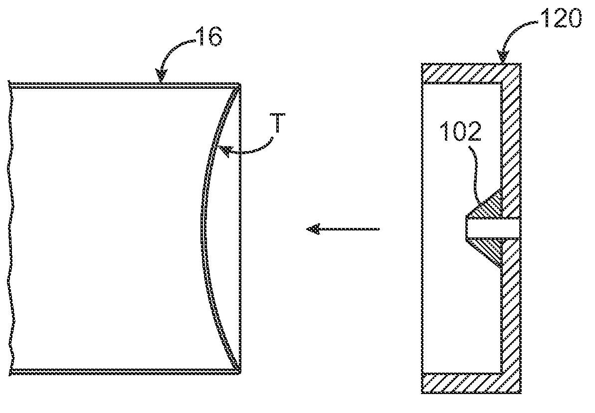
[0059]The process of converting an existing HIFU transducer is shown starting in FIG. 6A. Here the transducer T is shown mounted in a housing. A mold with an aperture 120 is fitted over the face of the transducer T and housing 16. Desirably the riser 102 touches the transducer front face when the guide ring is properly fit around the transducer housing. The mold with aperture 120 is desirably secured to the transducer housing so the mold will not move or become unstable during the process steps which follow. Once the mold with aperture 120 is properly placed over the transducer, the surface of the transducer may be roughened to promote physical adhesion of the shield later on. Various mechanisms may be used to roughen the transducer surface. Methods using lasers, chemicals, mechanical etching (such as sand blasting shown in FIG. 6C), or grinding (FIG. 6C′) may be used.

[0060]The back of the transducer may be treated in a similar fashion allowing for the removal of...

example ii

Aperture with Filler

[0063]In another example, the transducer with a shield may be formed by removing the region of the transducer which is designated to be non-driven. This can be accomplished in a variety of ways. In one embodiment of creating the non-driven region by removal, the material within the volume of the transducer designated to be non-driven can be physically removed. The transducer may be supported in any appropriate fashion and the appropriate volume removed by drilling it out, cutting it out, or otherwise destroying that designated volume of piezoelectric material

[0064]Once the appropriate volume has been removed, the edges of the aperture are desirably smoothed to provide an even edge for uniform ultrasound generation of the remainder of the transducer. The aperture may now be lined with a non conductive material to preserve the integrity of the circuit, and provide enhanced structural integrity around the rim of the aperture. In addition, the aperture may now be fil...

example iii

Non-Driven Ceramic

[0066]In yet another embodiment, the non-driven region may be created by purposely rendering the ceramic in the non-driven region unresponsive to electrical impulses by cutting the metallization layer prior to the poling step. This would cause an insulating gap in the metallization layer rendering the isolated portion electrically inactive. The desired polarizing effect within the isolated piezoelectric material would not be produced.


PUM


Abstract

A physical shield placed on the face of a high intensity focused ultrasound transducer for medical applications is described. The shield may be shaped or angled to match a particular pattern of mechanical or acoustic energy that may damage the transducer during operation. The shield may be ablative, replaceable or modified as needed. Methods of manufacturing a transducer with a shield are also disclosed.

Description

BACKGROUND OF THE INVENTION[0001]1. Field of the Invention[0002]The present invention relates to a high intensity focused ultrasound transducer for medical applications, the transducer generally having a shield physically attached to the transducer face.[0003]2. Description of the Background Art[0004]High intensity focused ultrasound (HIFU) transducers are finding increased usage in medical procedures. Similar to their cousins in diagnostic imaging, HIFU transducers share many of the same structural components. In HIFU transducers, the piezoelectric material is selected and crafted to produce the desired frequency, intensity, and total power to produce HIFU levels sufficient to lyse targeted tissue. Once a piezoelectric material has been selected and shaped, the piezoelectric material is coated with an electrically conductive material (a metallization layer) on both the front and back faces of the transducer. The piezoelectric material is ‘poled’ by applying a strong electric potent...

Claims


Application Information

Patent Timeline
Patent Type & Authority Patents(United States)
IPC IPC(8): H01L41/08H10N30/00
CPCG10K11/32B06B1/0681B06B1/0651A61B8/00H04R17/00H10N30/00
Inventor CRUNKILTON, JEFFREY R.DESILETS, CHARLES S.DARLINGTON, GREG P.QUISTGAARD, JENS U.
Owner LIPOSONIX
Learn More