Wavelength division multiplex (WDM) transmission system

a transmission system and wavelength division technology, applied in multiplex communication, instruments, cladded optical fibres, etc., can solve the problems of insufficient dispersion amount of compensator, difficult to measure large, and inability to meet the needs of large-scale communication, so as to speed up the recording of dispersion compensation amount and shorten the communication disruption time. , the effect of low cos

Inactive Publication Date: 2010-01-26
HITACHI LTD
View PDF12 Cites 9 Cited by
  • Summary
  • Abstract
  • Description
  • Claims
  • Application Information

AI Technical Summary

Benefits of technology

[0018]In view of the points described above, the objects of the present invention are to provide a low-cost variable dispersion compensator and to control at a high speed in a variable dispersion compensator for compensating wavelength dependent accumulated dispersion resulting from the wavelength dependency of transmission fiber and fixed dispersion compensators in a long-distance high-speed WDM transmission system.
[0022]According to the present invention, it will be possible to control with a low-cost configuration and at a high speed the wavelength dependency of residual dispersion that cannot be compensated even with fixed dispersion compensators by computing the dispersion compensation amount based on the input of the dispersion characteristics in the transmission line and at the representative wavelength of the DCF, using also the dispersion wavelength dependency characteristic recorded in advance in the control circuit and controlling the variable dispersion compensator.
[0023]And according to the present invention, it will be possible to control with a low-cost configuration and at a high speed the wavelength dependency of residual dispersion that cannot be compensated even with fixed dispersion compensators by searching and extracting the dispersion wavelength dependency recorded in advance in the transmission line taking the ID information of the transmission line and the DCF as index, by computing the dispersion compensation amount and by controlling the variable dispersion compensator.
[0024]And according to the present invention, it will be possible to control with a low-cost configuration and at a high speed the wavelength dependency of residual dispersion that cannot be compensated even by means of fixed dispersion compensators by searching and extracting the dispersion wavelength dependency recorded in advance in the control circuit taking the ID information of the transmission line and the DCF as index, by computing the dispersion compensation amount and by cooperatively controlling the optical cross-connect, or the optical add drop multiplexer and the variable dispersion compensator. And it will be possible to speed up the recording of dispersion compensation amount into a high-speed one during the switching time of routes on an optical cross-connect or an optical add-drop multiplexer, in other words to shorten the communication disruption time resulting from the switching of routes in an optical cross-connect or an optical add-drop multiplexer.

Problems solved by technology

However, if the measurement time is reduced, precision in the case of low number of errors falls down and consequently it is almost impossible to shorten too much the measurement cycle, and as a result it will be difficult to measure large error rates such as 10 to the minus fourth power or 10 to the minus third power, and in the case of severe signal degradation, the dispersion compensator often does not work well.
In addition, at the time of start-up of the variable dispersion compensator, the initial value of dispersion of the variable dispersion compensator is not always an adequate dispersion amount, and it is possible on the contrary that it has deviated from an appropriate dispersion amount.
As described above, if the signal degradation is severe, its function is normally difficult according to the traditional configuration shown in FIG. 18.
As a result, the start-up time becomes long, constituting a problem.
Moreover, a mechanism of measuring error rate is required for every signal wavelength, possibly resulting in a high cost of optical receiver.
In any case, however, expensive high-speed electric components are required and this constitute a problem with respect to costs.

Method used


Image

  • Wavelength division multiplex (WDM) transmission system
  • Wavelength division multiplex (WDM) transmission system
  • Wavelength division multiplex (WDM) transmission system

Examples


first embodiment

1. The First Embodiment

(1) WDM Transmission System

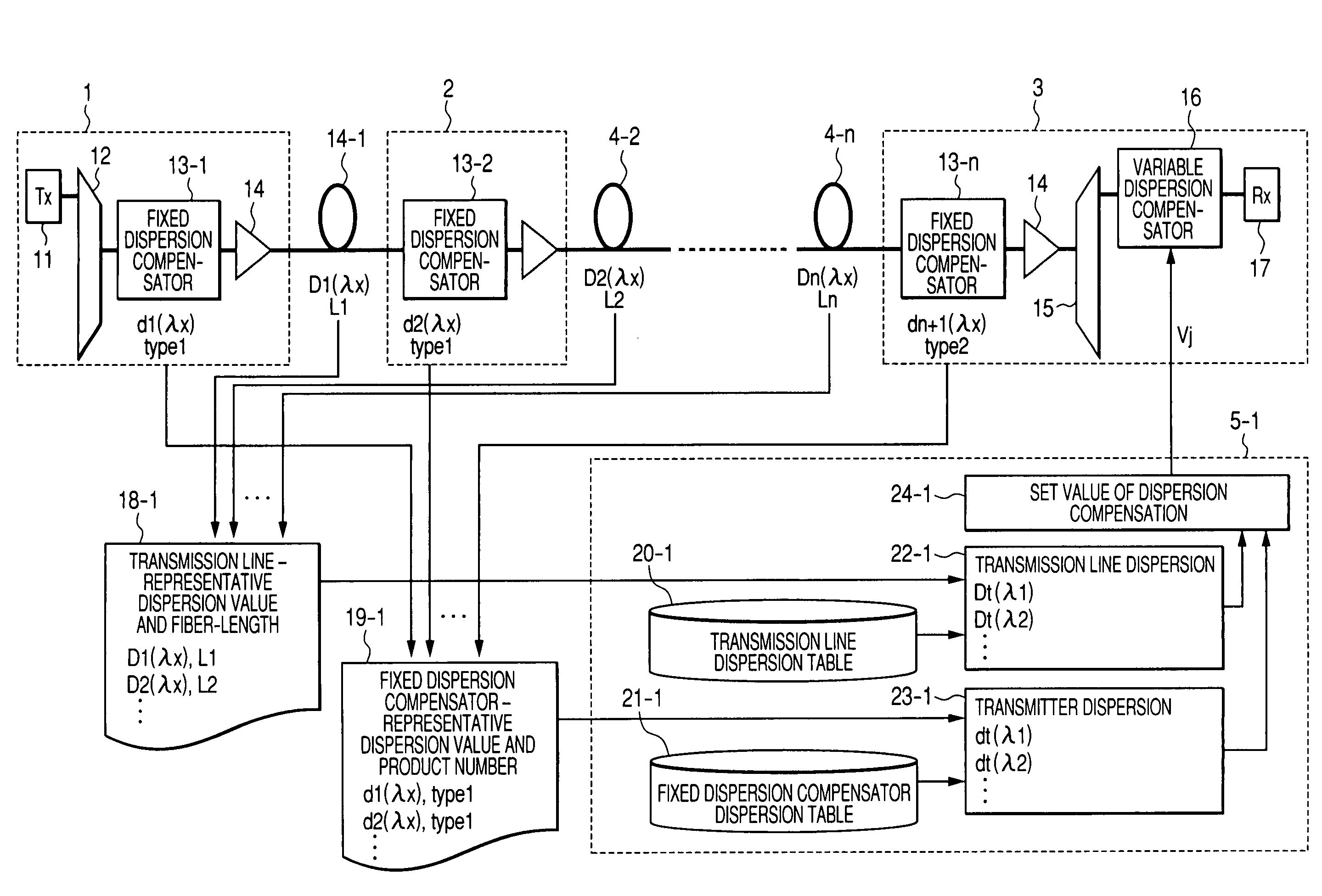
[0043]FIG. 1 shows the configuration of the first embodiment of the WDM transmission system.

[0044]We will describe below the first embodiment of the present invention.

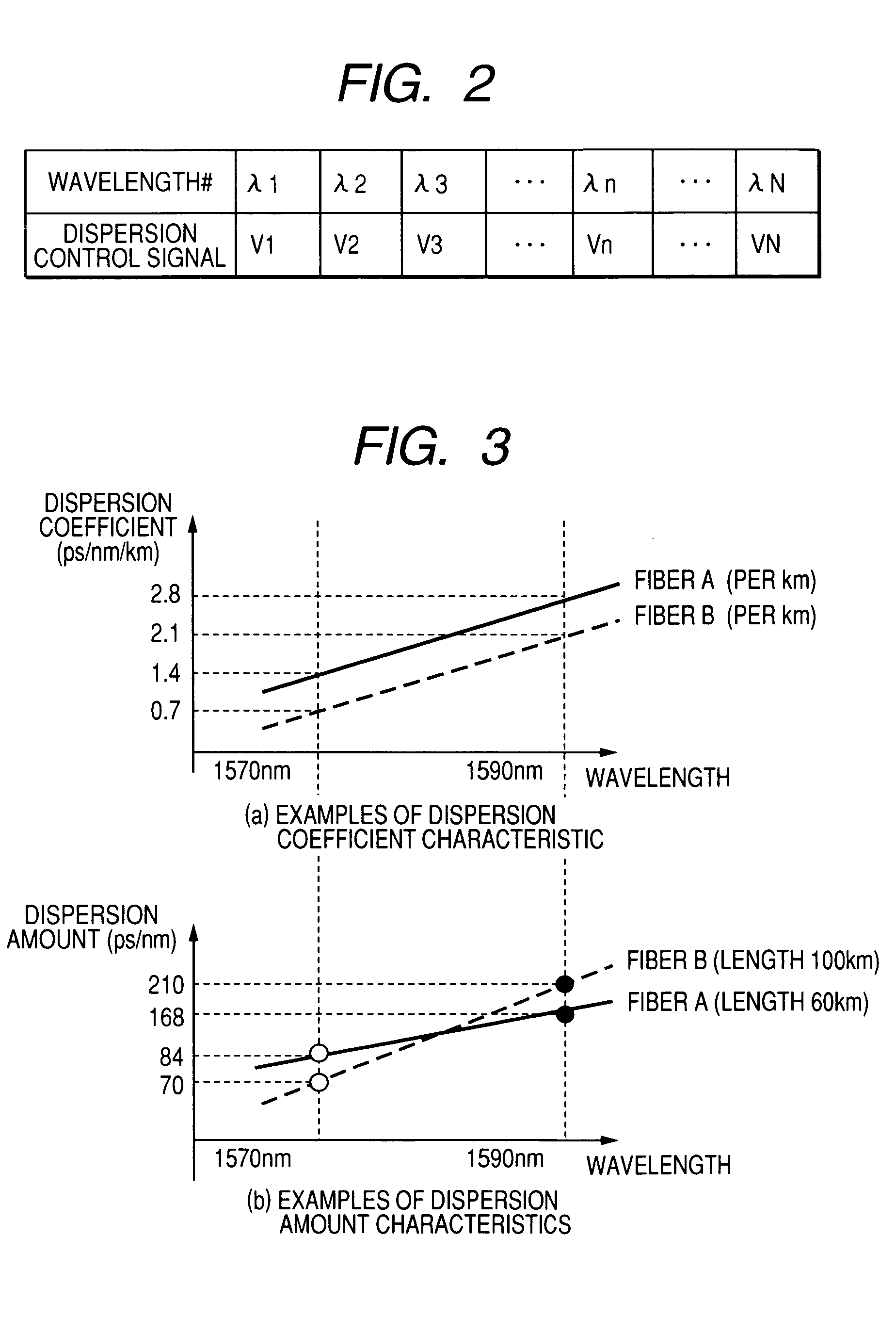
[0045]The WDM transmission system that we propose includes a WDM transmitter (1), a WDM relay (2), a WDM receiver (3), a control circuit (5-1), and respective fibers (4-1, 2, The WDM transmitter (1) comprises further an optical transmitter (11) for sending out modulated optical signals, a multiplexer (12) for multiplexing various signal wavelengths coming from the optical transmitter, fixed dispersion compensators (13-1) for compensating a fixed amount of dispersion and an optical amplifier (14). The WDM relay (2) comprises fixed dispersion compensators (13-2, 3, . . . ), and an optical amplifier (14). The WDM receiver (3) comprises fixed dispersion compensators (13-n), an optical amplifier (14), a multiplexer for separating the WDM signals to respective separate signal...

second embodiment

2. The Second Embodiment

(1) WDN Transmission System

[0095]FIG. 11 is a block diagram showing the configuration of the second embodiment of the WDM transmission system.

[0096]We will describe below the second embodiment of the present invention.

[0097]The WDN transmission system that we propose includes a WDM transmitter (1), a WDM relay (2), a WDM receiver (3), a control circuit (5-2) and respective fibers (4-1, 2, . . . n). The configuration of a WDM transmitter (1), a WDM relay (2), a WDM receiver (3) is similar to the first embodiment. The control circuit (5-2) is provided with a processor (22-2) for computing the dispersion amount in the transmission lines and the processor (23-2) for computing the dispersion amount of the fixed dispersion compensators. Each processor (22-2) and (23-2) is connected with a storage area, and in each storage area the dispersion data table (20-2) in the transmission lines and the dispersion data table (21-2) of the fixed dispersion compensators are con...

third embodiment

3. The Third Embodiment

(1) WDM Transmission System

[0116]FIG. 14 is a block diagram showing the configuration of the third embodiment of the WDM transmission system.

[0117]We will describe below the third embodiment of the present invention.

[0118]The WDM transmission system includes a WDM transmitter (1) and a WDM transmitter (51-3), a WDM relay (2) and a WDM relay (52), an optical cross-connect (31), a WDM receiver (3), a control circuit (5-3), a switch controller (27) and respective fibers (4-1, 2, . . . ) and (4-51). The configuration of a WDM transmitter (1), a WDM relay (2), a WDM receiver (3) is similar to the first and the second embodiments. The WDM transmitter (51-3) includes an optical transmitter (11), a multiplexer (12), a fixed dispersion compensator (13-51), and an optical amplifier (14). The control circuit (5-3) is provided with a processor (22-3) for computing the dispersion amount in the transmission lines and the processor (23-3) for computing the dispersion amount ...


PUM


Abstract

A low-cost configuration of, and at the same time to control the variable dispersion compensator at a high speed in a variable dispersion compensator for compensating the wavelength dependent accumulated dispersion resulting from the wavelength dependency of the transmission fiber and fixed dispersion compensator in a long-distance high-speed WDM transmission system. In order to achieve the object mentioned above, the wavelength dependent representative characteristic of the transmission fibers 4-1 . . . n, and the wavelength dependent representative characteristic of the DCFs 13-1 . . . n are recorded and maintained in advance in the dispersion control circuit 5-1 . . . n of the variable dispersion compensator 16, and based on the input of dispersion amount at the representative length of the transmission fiber and the fiber length, the dispersion amount at the representative wavelength of the DCF, the accumulated dispersion amount is computed from the wavelength dependent representative characteristic recorded and maintained in advance, and the dispersion amount of the variable dispersion compensator 16 is determined by taking this as the reference.

Description

CLAIM OF PRIORITY[0001]The present application claims priority from Japanese application JP 2006-020529 filed on Jan. 30, 2006, the content of which is hereby incorporated by reference into this application.FIELD OF THE INVENTION[0002]The present invention relates to a WDM (Wavelength Division Multiplex) transmission system, in particular to a WDM transmission system wherein any residual dispersion dependent on wavelength that may have developed when the dispersion of the transmission fiber is compensated by a fixed dispersion compensator can be compensated by the variable dispersion compensator.BACKGROUND OF THE INVENTION[0003]In the high-speed optical fiber communication, light waveform may sometimes deteriorate limiting transmission speed and transmission distance due to a characteristic of wavelength dispersion in the fiber. Wavelength dispersion (hereinafter referred to as “dispersion”) means the wavelength dependence of group velocity at which signals propagate in the optical ...

Claims


Application Information

Patent Timeline
Patent Type & Authority Patents(United States)
IPC IPC(8): H04B10/12H04B10/18H04B10/2507H04B10/2519H04B10/2525H04J14/00H04J14/02
CPCH04B10/25133H04J14/02H04J14/0279H04J14/0212
Inventor SEKINE, KENRO
Owner HITACHI LTD
Why Eureka
Try Eureka