Can-filter structure of oxygen concentrator

a technology of oxygen concentrator and can filter, which is applied in the direction of respirator, filtration separation, and separation process, can solve the problems of poor air tightness, bulky oxygen concentrators, and unsuitable for automobile use or as portable devices, and achieves easy detachability and good air tightness

Inactive Publication Date: 2010-02-02
TREATYOU MEDICAL TECH CORP
View PDF8 Cites 30 Cited by
  • Summary
  • Abstract
  • Description
  • Claims
  • Application Information

AI Technical Summary

Benefits of technology

[0010]An object of the invention is to provide a can-filter structure of oxygen concentrator, which has an improved design to cure the aforementioned defects of the oxygen concentrator, and the can-filter structure is compact, lightweight, easily detachable, and has good air tightness.
[0013]The second can-filter includes a second hollow second filter can, which has an entrance side and an exit side, and a hollow second conical joint provided at the entrance side of the second filter can, wherein a second tubular portion is integrally formed between the narrow end of the second conical joint and the entrance side of the second filter can. When the first can-filter and the second can-filter are connected, the second tubular portion is mounted around the periphery of the first tubular portion, and the aforementioned airtight sealing ring is disposed between the two tubular portions to create an airtight effect. Moreover, the outlet cover with a 90 degrees bend is provided at the exit side of the second filter can and is coupled to the second filter can by ultrasonic fusion.
[0014]Furthermore, the first conical joint of the first can-filter and the second conical joint of the second can-filter are respectively provided with, on their surfaces, a double-recess structure and a double-engagement hook structure that correspond to one another and the recesses / resilient engaging hooks are arranged at equally spaced positions in the circumferential direction for engaging with one another. The engagement detachably fastens the first conical joint and the second conical joint, making the assembly of the first can-filter and the second filter more secure and easier to disassemble. The elements of the invention are formed and coupled by ultrasonic fusion, thus excellent fixity is achieved.

Problems solved by technology

However, due to the complexity of the internal assembly, most of the replacement and disassembling operations are performed by professional technicians, which is very inconvenient to the users.
Moreover, most of the oxygen concentrators are bulky in size and are unsuitable for use in automobiles or as portable devices.
This operation process is complicated and results in poor air tightness, which is prone to air leakage.
In addition, conventionally, the outlet of the second can-filter in PSA oxygen generators is a straight round pipe, but such design would cause a hose, which is used to connect between the pipe and other devices, to deform at turns.
The deformation of hose would block airflow, making the air to flow not as smoothly or the local pressure to be high, and in turn causes air leakage or damages to the elements.
Furthermore, the hose used for connection has to be detached when replacing can-filters, thus it is very inconvenient to use.

Method used


Image

  • Can-filter structure of oxygen concentrator
  • Can-filter structure of oxygen concentrator
  • Can-filter structure of oxygen concentrator

Examples


Embodiment Construction

[0020]The can-filter structure according to preferred embodiments of the invention will be described in detail with reference to the drawings, in which like reference numerals denote like elements.

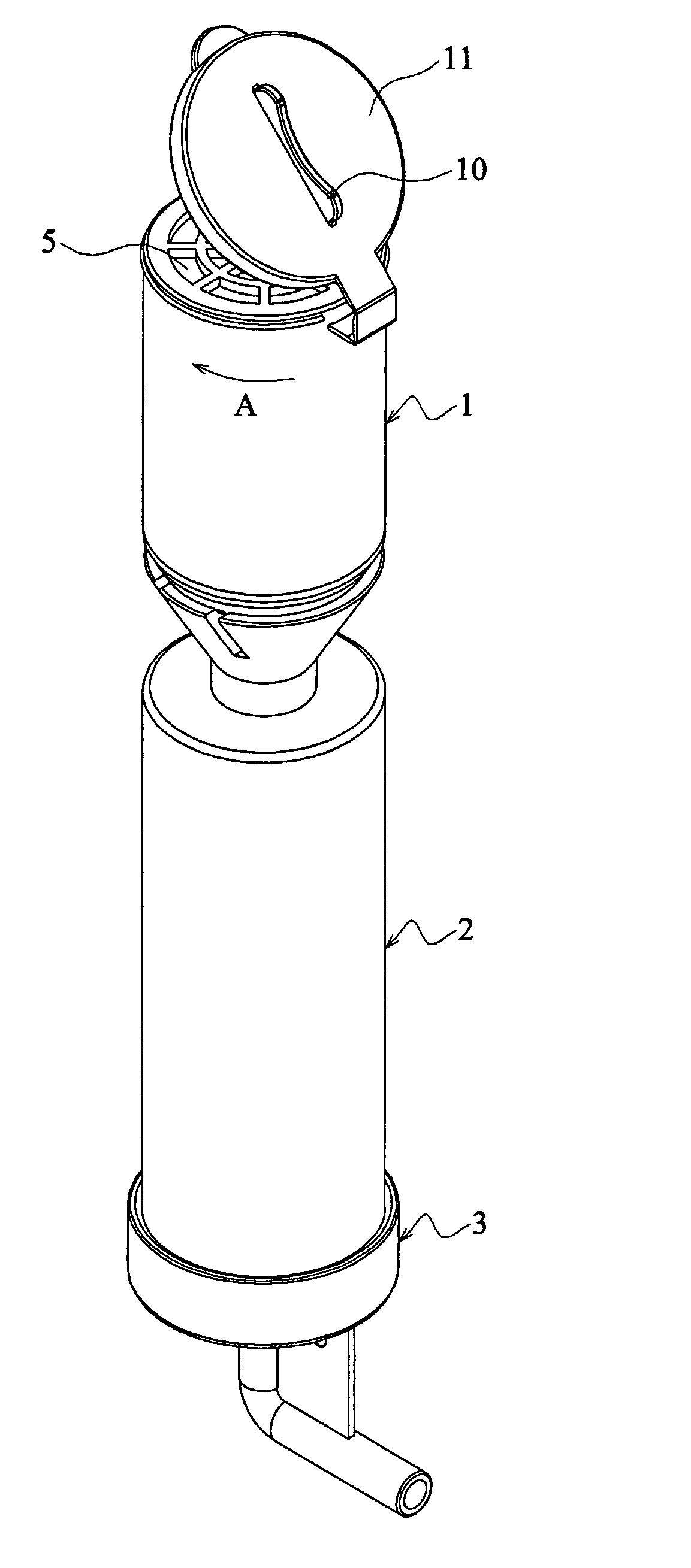
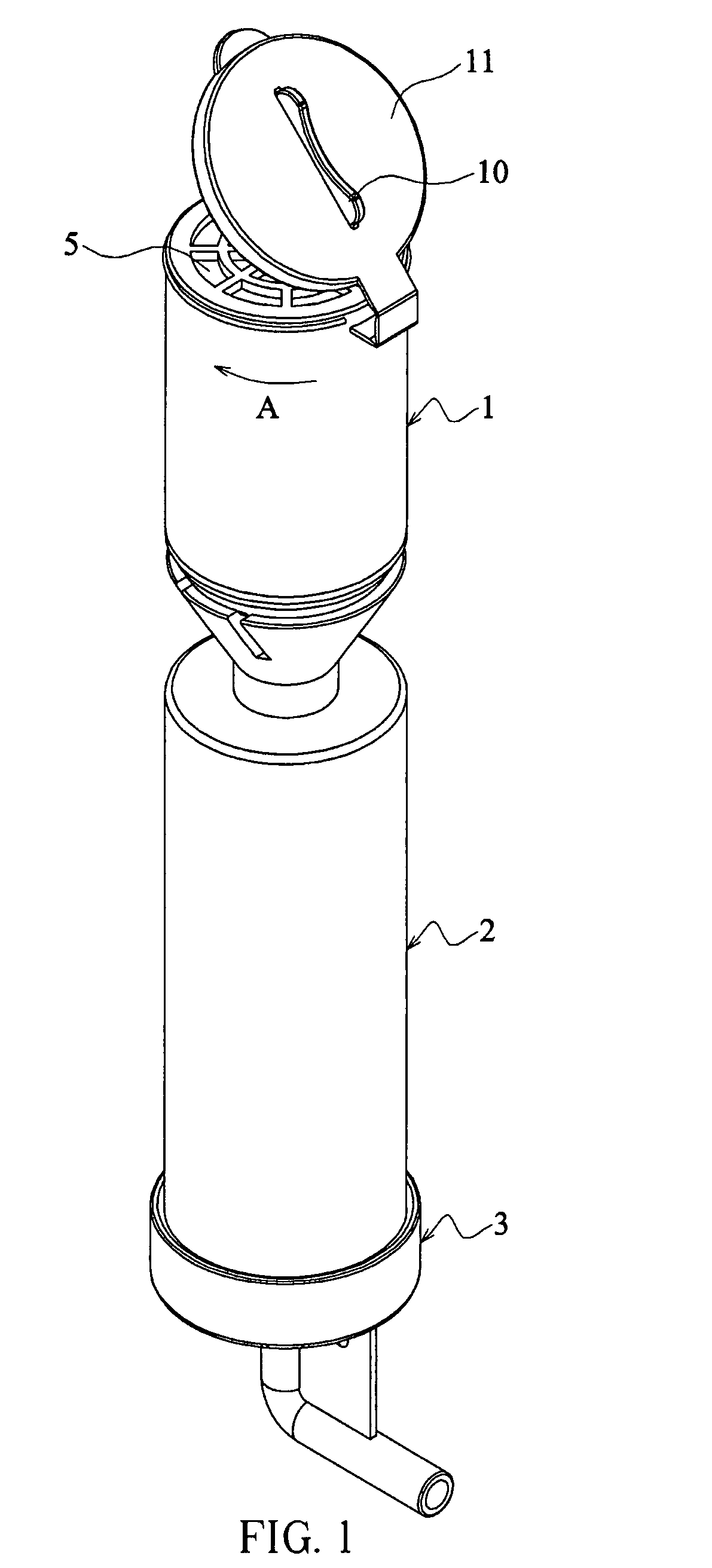
[0021]FIG. 1 is a pictorial view of a can-filter structure according to an embodiment of the invention. The can-filter structure includes: a first can-filter 1 with an entrance side and an exit side, a second can-filter 2 with an entrance side and an exit side, and an outlet cover 3. The first can-filter 1 includes an air inlet 5 provided at the entrance side and a lid 11 disposed at the air inlet 5 so as to open and close the air inlet 5; a wing-shaped grip 10 is disposed on the one side of the lid 11 opposite the air inlet 5. The exit side of the first can-filter 1 is connected to the entrance side of the second can-filter 2, and the exit side of the second can-filter 2 is overlaid with the outlet cover 3. The first can-filter 1 and the second can-filter 2 are hollow structures filled th...


PUM

PropertyMeasurementUnit
resilientaaaaaaaaaa
concentrationsaaaaaaaaaa
concentrationaaaaaaaaaa

Abstract

The invention is a can-filter structure of an oxygen concentrator, which includes: a first can-filter having filter material; a second can-filter having filter material; and an outlet cover. The first can-filter includes an air inlet provided at the entrance side of the first can-filter and a first conical joint formed at the exit side of the first can-filter, wherein the first conical joint is hollow and at least one recess is provided on the outer surface thereof. The second can-filter includes a second conical joint formed at the entrance side of the second can-filter, wherein the second conical joint is hollow, and at least one engaging hook corresponding to the recess is provided on the inner surface thereof for coupling to the first conical joint. The outlet cover is provided at the exit side of the second can-filter and is coupled thereto by ultrasonic fusion.

Description

BACKGROUND OF THE INVENTION[0001]a) Field of the Invention[0002]The invention relates to a can-filter structure of oxygen concentrator and, more particularly, to a can-filter structure of household or personal PSA oxygen concentrator.[0003]b) Description of the Related Art[0004]An oxygen concentrator provides oxygen at substantially higher concentrations than those of ambient air. The oxygen concentration in general ambient air is around 20%, but it would help a person to recover from tiredness and release pressure after high-intensity exercises if the oxygen concentration is raised to about 30% to 35%. Moreover, patients with respiratory problems like asthma need highly concentrated oxygen for medical and heath care purposes.[0005]Common methods used to supply oxygen include: 1) pressure swing adsorption (PSA), 2) electrolysis, and 3) usage of oxygen tank. The PSA method is to obtain oxygen from ambient air, wherein through the work of a molecular sieve in the oxygen concentrator, ...

Claims


Application Information

Patent Timeline
Patent Type & Authority Patents(United States)
IPC IPC(8): B01D39/00
CPCB01D46/0013B01D46/0024B01D46/008B01D46/30B01D46/64B01D46/88
Inventor WANG, SHIOW-CHENYANG, WEN-FENGWU, WEN-CHING
Owner TREATYOU MEDICAL TECH CORP
Why Eureka
Try Eureka