Membrane pipe module

a membrane pipe and tube technology, applied in the field of tube modules, can solve the problems of reducing the driving force, affecting the performance of the process, and blocking the flux through the membrane,

Inactive Publication Date: 2010-02-02
SULZER CHEMTECH - MEMBRANTECHN
View PDF18 Cites 9 Cited by
  • Summary
  • Abstract
  • Description
  • Claims
  • Application Information

AI Technical Summary

Benefits of technology

[0006]The task is solved in the present invention by a tube module in which a multitude of tubular membrane segments is arranged in a cylindrical housing in an axial direction, these segments, if necessary, being at their ends partially interconnected with each other, forming longer tubular membrane segments, and characterized by the fact that said tube module is provided at one or both ends of the cylindrical housing with each a heating chamber, these heating chambers provided with U-shaped interconnecting tubes, the open ends of these U-shaped tubes leading through a wall separating the heating chambers and the housing, and connecting two adjacent open tubular membrane segments, forming a tubular membrane infinite loop.

Problems solved by technology

In the process of pervaporation for the separation of liquid mixtures the heat for the evaporation of the permeate is taken from the sensible heat of the liquid mixture, the thus caused decrease in temperature leads to a reduction of the driving force, and hence the flux through the membrane, and thus to a decrease in the performance of the process.
In the separation of vaporous or gaseous mixtures unavoidable heat losses may lead to a cooling of the feed mixture and condensation of components out of the mixture, as a consequence blocking of the flux through the membrane can occur.
After leaving the intermediate heat exchanger and entrance into the module no supply of heat is possible in the tube modules of the state-of art technology.
Especially in tube modules with long membrane tubes or flexible hoses and a respectively large membrane area combined with a large amount of permeate significant cooling of the feed mixture may occur which will affect the separation or stop it at all.
The thereby unavoidable limitation in membrane area per module, the required number of intermediate heat exchangers, the additionally necessary piping connection between these apparatus and the additional expenses for controls lead to an uneconomical increase in the specific costs per membrane area installed.

Method used


Image

  • Membrane pipe module
  • Membrane pipe module
  • Membrane pipe module

Examples


Embodiment Construction

Of THE INVENTION

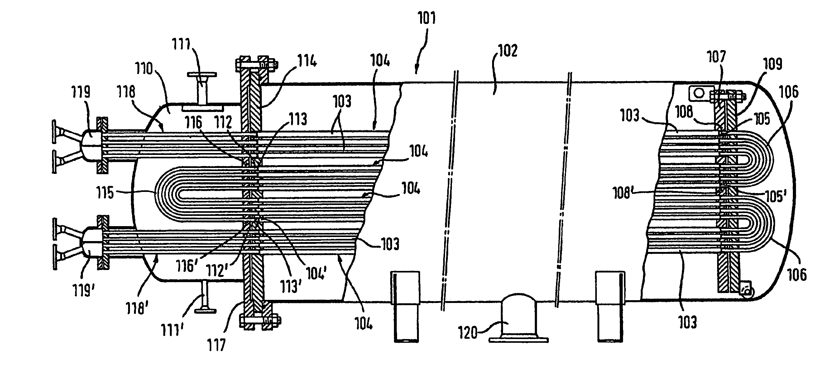
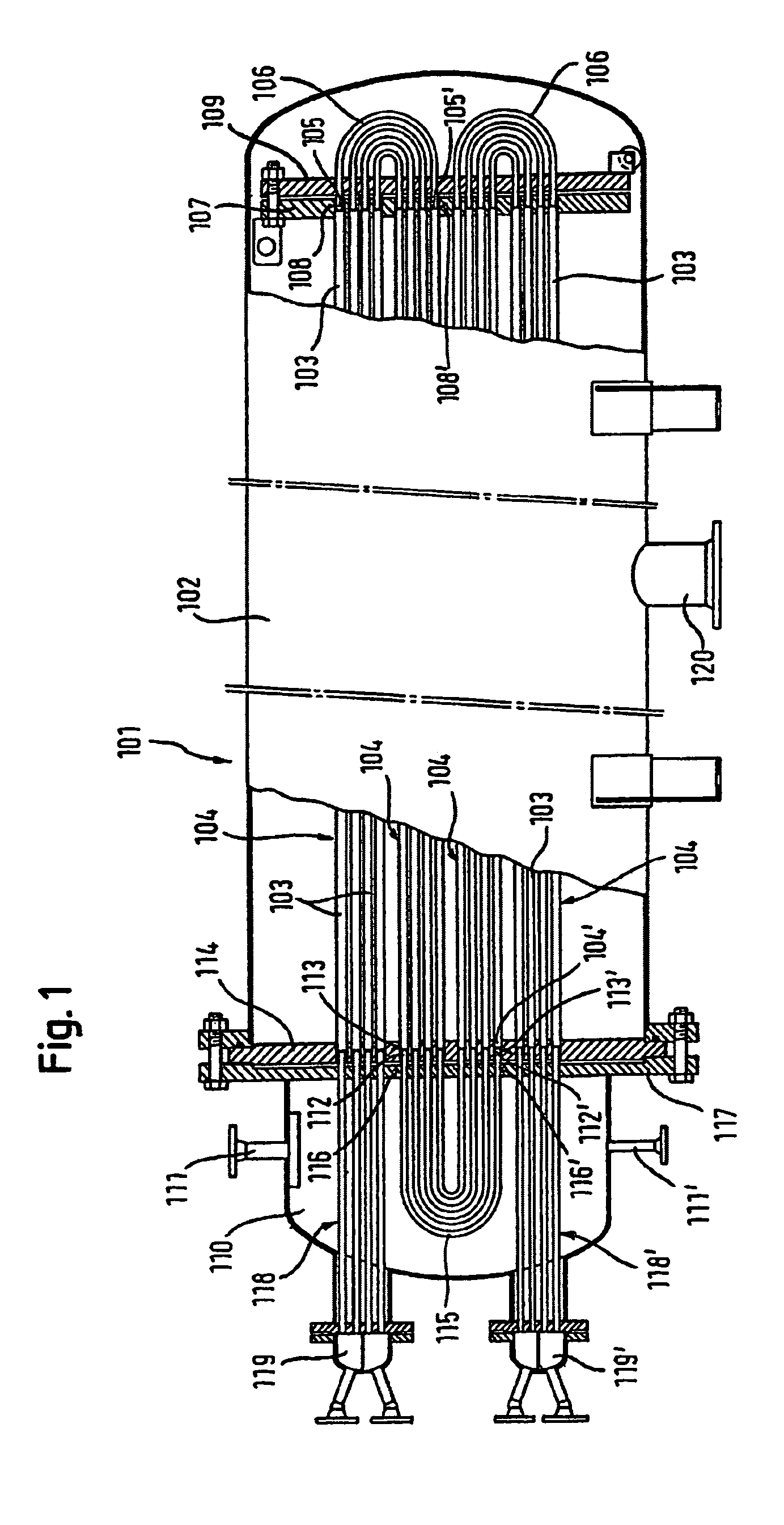
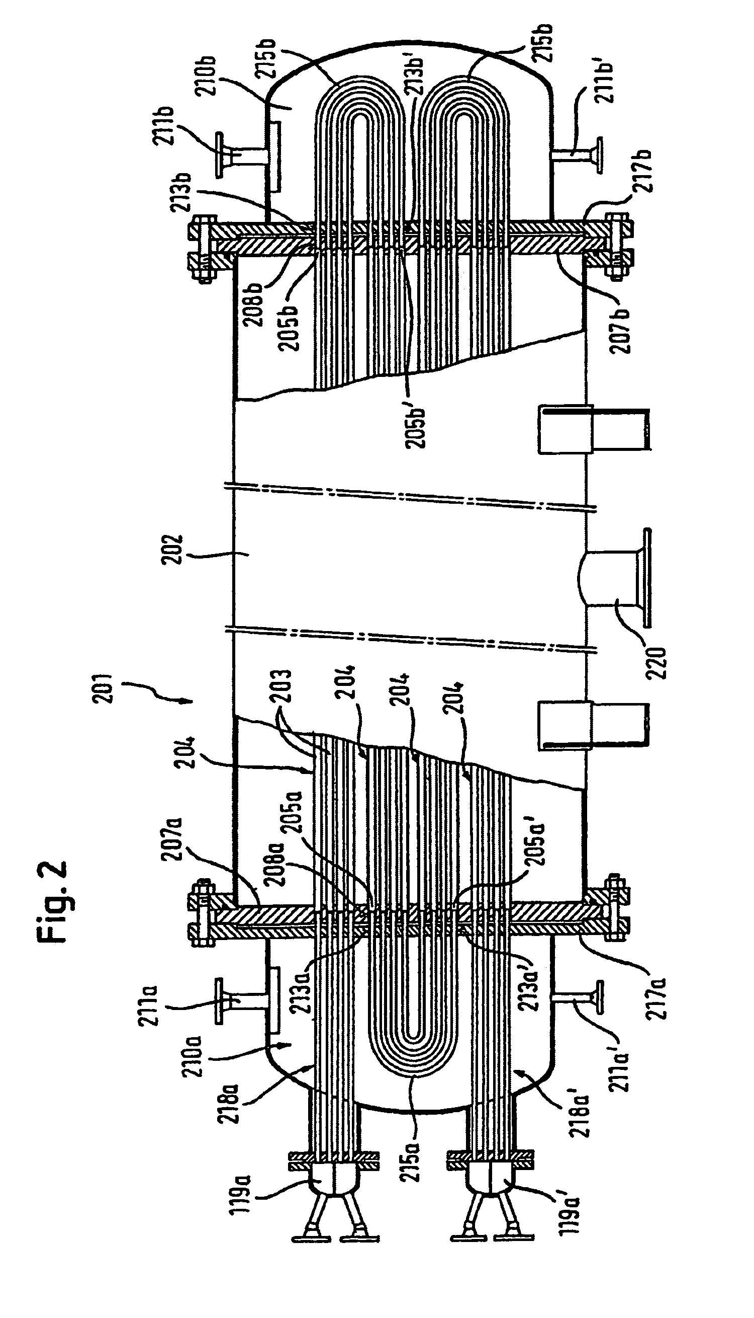
[0009]In the state-of-art tube modules the tubular membrane segments arranged in a cylindrical housing are interconnected at their ends forming infinite membrane tubes. The tube module of the present invention differs from the state-of-art by the fact that a certain number of adjacent tubular membrane segments at one or both ends of the cylindrical housing is left open, these ends being connected by said U-shaped interconnecting tubes which lead with their open ends through the wall separating the cylindrical housing and the heating chamber. The feed mixture to be separated passes through the U-shaped interconnecting tubes inside the heating chambers where the required heat can be supplied. The heating chambers thus function as heat exchangers the heat being supplied e.g. by steam or another heat transfer medium.

[0010]In a preferred embodiment of the tube module of the present invention the tubular membrane segments are fixed at one end or at both ends in a plate pro...


PUM

PropertyMeasurementUnit
diameteraaaaaaaaaa
diameteraaaaaaaaaa
diametersaaaaaaaaaa

Abstract

The invention relates to a membrane pipe module, said module comprising a cylindrical housing containing a plurality of tubular membrane sections which extend in the axial direction and are interconnected at the ends thereof, forming longer tubular membrane sections. Said cylindrical housing comprises a heatable chamber, on one or both sides, comprising U-shaped connection pipes which are arranged therein and are guided through a separating wall between the chamber and the housing, with the two open ends thereof, and respectively connect two adjacent open tubular membrane sections, forming a membrane loop.

Description

CROSS-REFERENCE TO RELATED APPLICATIONS[0001]This application is a U.S. National Phase Application of PCT International Application PCT / EP2004 / 005405, filed May 19, 2004.FIELD OF THE INVENTION[0002]The invention relates to a tube module comprising tubular membranes and integrated heat exchange.BACKGROUND OF THE INVENTION[0003]The membranes used in membrane technology for the separation of liquid or gaseous mixtures are incorporated in useful arrangement in modules. General known forms of such modules are those with pleated membranes, plate modules, and spiral wound modules on one side, and hollow fiber, capillary, tubular, or tube modules on the other side. The first group of modules is used for flat sheet membranes, the second one for membranes in tubular form. The diameter of the respective tubular membranes vary between 30μ to 100μ for hollow fiber modules, between 0.2 mm to 3 mm for capillary modules, and in the range between 4 mm to 50 mm for tubular or tube modules. The transm...

Claims


Application Information

Patent Timeline
Patent Type & Authority Patents(United States)
IPC IPC(8): B01D63/06B01D61/36B01D61/00B01D65/00
CPCB01D61/362B01D63/06B01D63/063B01D65/00B01D2313/13B01D2313/23B01D2319/022
Inventor BRUSCHKE, HARTMUT E. A.WYNN, NICHOLAS PATRICKMARGGRAFF, FRANK-KLAUS
Owner SULZER CHEMTECH - MEMBRANTECHN
Why Eureka
Try Eureka