
Membranes for an analyte sensor

a technology of analyte sensor and membrane, which is applied in the field of glucose measurement devices, can solve the problems of inability to know the blood glucose value of the patient, incur dangerous side effects, and physiological derangements,

Inactive Publication Date: 2007-07-26
DEXCOM
View PDF98 Cites 437 Cited by
  • Summary
  • Abstract
  • Description
  • Claims
  • Application Information

AI Technical Summary

Benefits of technology

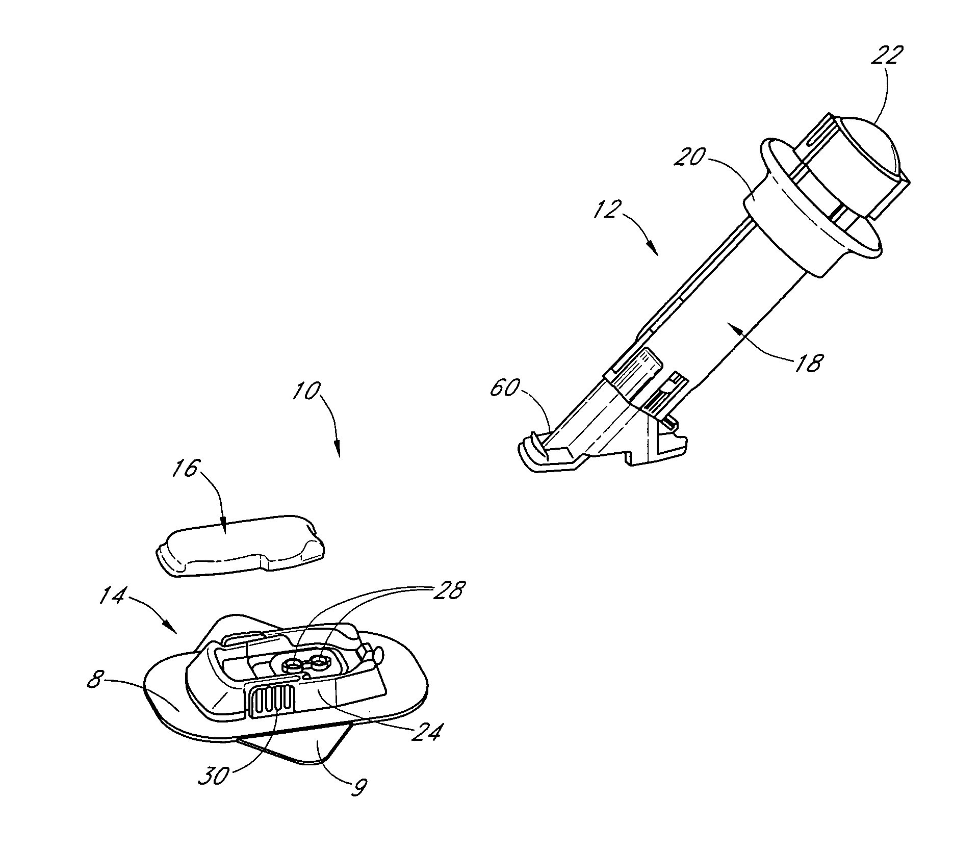
[0007] In a first aspect, an electrochemical analyte sensor configured for implantation in vivo and for measuring an analyte concentration in a host is provided, the sensor comprising at least one electroactive surface; and a membrane system dis...

Problems solved by technology

In the diabetic state, the victim suffers from high blood sugar, which can cause an array of physiological derangements associated with the deterioration of small blood vessels, for example, kidney failure, skin ulcers, or bleeding into the vitreous of the eye.
Conventionally, a person with diabetes carries a self-monitoring blood glucose (SMBG) monitor, which typically requires uncomfortable finger pricking methods.
Unfortunately, such time intervals are so far spread apart that the person with diabetes likely finds out too late of a hyperglycemic or hypoglycemic condition, sometimes incurring dangerous side effects.
It is not only unlikely that a person with diabetes will take a timely SMBG value, it is also likely that he or she will not know if his or her blood glucose value is going up (higher) or down (lower) based on conventional method.
This inhibits the ability to make educated insulin therapy decisions.
One problem with electrochemical sensors is that they can electrochemically react not only with the analyte to be measured (or by-product of the enzymatic reaction with the analyte), but additionally can react with other electroactive species that are not intentionally being measured (for example, interfering species), which causes an increase in signal strength due to these “interfering species.” In other words, interfering species are compounds with an oxidation or reduction potential that overlaps with the analyte to be measured (or by-product of the enzymatic reaction with the analyte).
For example, in a conventional amperometric glucose oxidase-based glucose sensor wherein the sensor measures hydrogen peroxide, interfering species such as acetaminophen, ascorbic acid, and uric acid, are known to produce inaccurate glucose signal amplitude when they are not properly controlled.

Method used


Image

  • Membranes for an analyte sensor
  • Membranes for an analyte sensor
  • Membranes for an analyte sensor

Examples


example 1

Transcutaneous Glucose Sensor with Cellulose Acetate Interference Domain

[0647] A short term (transcutaneous) sensor was built by providing a platinum wire, vapor-depositing the platinum with Parylene to form an insulating coating, helically winding a silver wire around the insulated platinum wire (to form a “twisted pair”), masking sections of electroactive surface of the silver wire, vapor-depositing Parylene on the twisted pair, chloridizing the silver electrode to form silver chloride reference electrode, and removing a radial window on the insulated platinum wire to expose a circumferential electroactive working electrode surface area thereon, this assembly also referred to as a “parylene-coated twisted pair assembly.”

[0648] An interference domain was formed on the parylene-coated twisted pair assembly by dip coating in an interference domain solution comprising 7 wt. %, 50,000 molecular weight cellulose acetate (Sigma-Aldrich, St. Louis, Mo.) in a 2:1 acetone / ethanol solvent ...

example 2

Transcutaneous Glucose Sensor with Cellulose Aacetate / Nation® Interference Domain

[0651] Transcutaneous glucose sensors with a cellulose acetate / Nation® interference domain (CA / Naf sensors) were constructed as described with reference to the transcutaneous glucose sensors with a cellulose acetate interference domain above; however, after dip coating the parylene-coated twisted pair assembly in the cellulose acetate solution, the cellulose acetate coated assembly was further dip coated in a 5 wt. % Nation® solution in low aliphatic alcohols (Sigma-Aldrich, St. Louis, Mo.) and allowed to dry at room temperature for 10 minutes. This Nation® solution dip coating step was repeated twice to form three layers of Nation® over the cellulose acetate layers. Enzyme and resistance domains were subsequently coated onto the cellulose acetate / Nation® interference domain coated assembly, and selected test sensors were exposed to electron beam radiation, as described in more detail above.

example 3

In Vitro Testing

[0652] In vitro tests were run to evaluate the ability of the above-described sensors to resist uric acid, ascorbic acid, and acetaminophen. Namely, four CA sensors (two before and two after electron beam exposure) were immersed in 40, 200, and 400 mg / dL glucose while their electrical signal was monitored. Subsequently, the sensors were immersed into a solution containing 400 mg / dL glucose plus one of either 0.5 mM uric acid (FIG. 24A), 0.23 mM ascorbic acid (FIG. 24B), or 0.22 mM acetaminophen (FIG. 24C).

[0653]FIG. 24A is a bar graph that illustrates the ability of the CA sensors to resist uric acid pre- and post-electron beam exposure. The x-axis represents the sensors involved in the in vitro testing. Namely, 3CA represents an interference domain formed on sensors comprised of four dip coated layers of cellulose acetate as described above. Half of the CA sensors were tested pre-electron beam exposure and half of the sensors were tested post-electron beam exposu...


PUM

PropertyMeasurementUnit
Timeaaaaaaaaaa
Timeaaaaaaaaaa
Concentrationaaaaaaaaaa

Abstract

The present invention relates generally to devices for measuring an analyte in a host. More particularly, the present invention relates to devices for measurement of glucose in a host that incorporate a hydrophilic electrode domain and / or a cellulosic-based interference domain.

Description

RELATED APPLICATIONS [0001] This application is a continuation-in-part of U.S. application Ser. No. 11 / 335,879, filed Jan. 18, 2006, which claims priority under 35 U.S.C. § 119(e) to U.S. Provisional Application No. 60 / 669,851, filed Apr. 8, 2005. This application is a continuation-in-part of U.S. application Ser. No. 11 / 413,238 filed Apr. 28, 2006, U.S. application Ser. No. 11 / 413,242 filed Apr. 28, 2006, and U.S. application Ser. No. 11 / 413,356 filed Apr. 28, 2006, each of which claims priority under 35 U.S.C. § 119(e) to U.S. Provisional Application No. 60 / 678,373, filed May 5, 2005. Each of the above-referenced applications is hereby incorporated by reference herein in its entirety, and is hereby made a part of this specification.FIELD OF THE INVENTION [0002] The present invention relates generally to devices for measuring an analyte in a host. More particularly, the present invention relates to devices for measurement of glucose in a host that incorporate a cellulosic-based int...

Claims


Application Information

Patent Timeline
IPC IPC(8): A61B5/05
CPCA61B5/14532A61B5/6849A61B5/14865A61B5/1468A61B5/1473A61B5/686C12Q1/002C12Q1/003
Inventor PETISCE, JAMESWOO, KUMNICHOLAS, MELISSACAMPBELL, REBECCATRAN, OLIVIA
Owner DEXCOM
Learn More