
Valvuloplasty devices and methods

a valvuloplasty and device technology, applied in the field of balloon catheters, can solve the problems of limiting the ability of valvular heart disease acquisition, reducing the effectiveness of therapy, and reducing the possibility of intracardiac trauma, so as to reduce the risk of intracardiac trauma, and reduce the risk of injury

Active Publication Date: 2005-04-28
INTERVALVE MEDICAL INC
View PDF39 Cites 444 Cited by
  • Summary
  • Abstract
  • Description
  • Claims
  • Application Information

AI Technical Summary

Benefits of technology

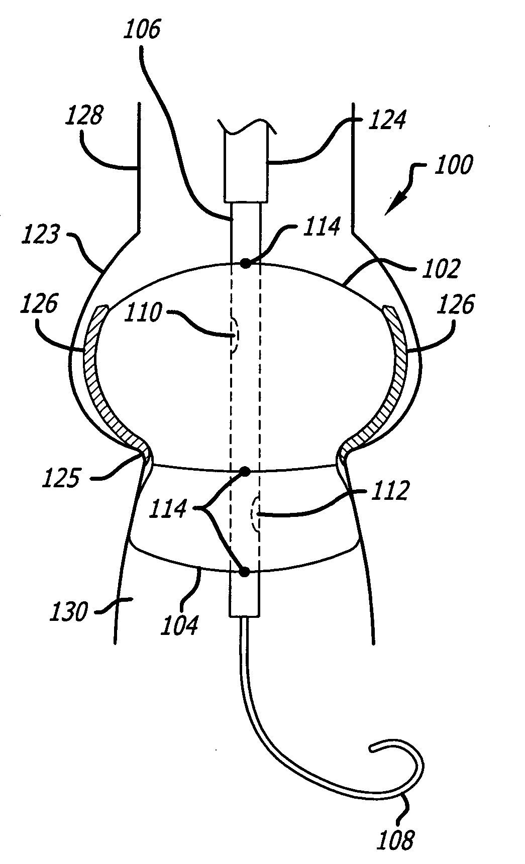
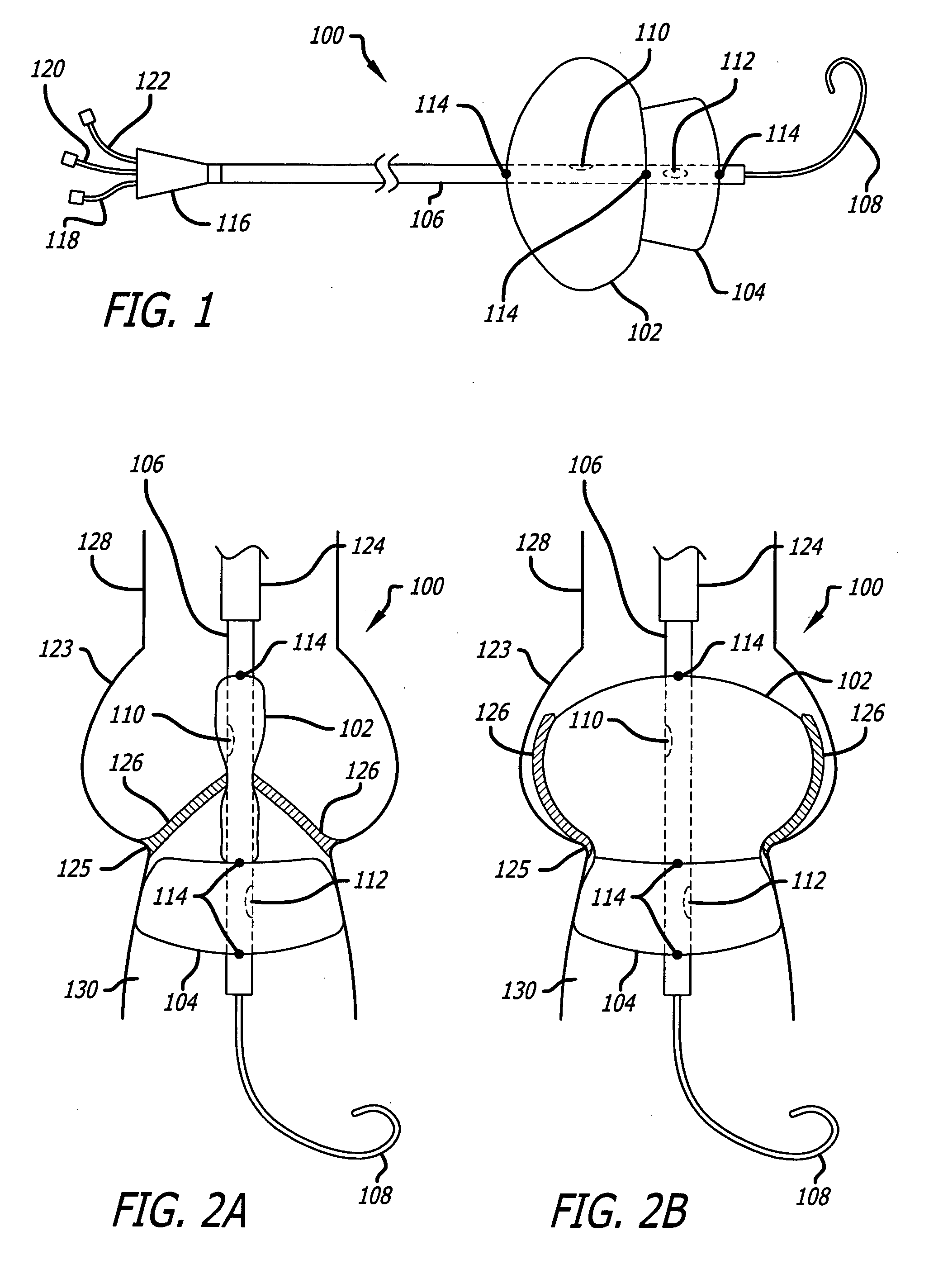
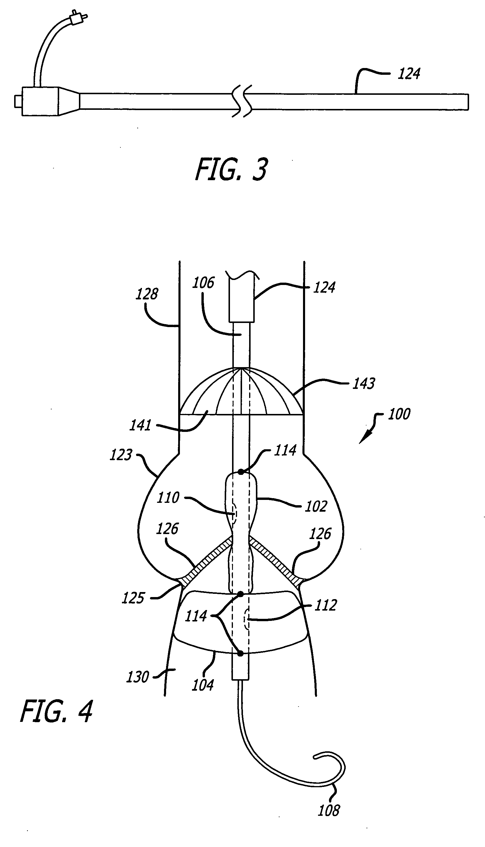
"The present invention provides a balloon catheter for valvuloplasty that overcomes shortcomings of prior art. The catheter has a tapered distal balloon segment that anchors within the left ventricle outflow track and a more proximal rounded segment to broadly dilate the aortic valve leaflets into the aortic root sinuses. The catheter has a fiber-based balloon membrane to achieve a lower profile, higher pressure balloon with a specific geometric shape. It also allows for distal perfusion while the balloon is inflated and has a pigtail distal tip to minimize likelihood of intracardiac trauma. The entire catheter may be advanced through an elongated sheath to assure greater stability and permit measurement of central aortic pressures."

Problems solved by technology

Calcific aortic stenosis is a common cause of acquired valvular heart disease with substantial morbidity and mortality.
Over time, as fibrosis and calcification worsens, valve leaflets become increasingly rigid, restricting their ability to open.
This in turn, then impedes the antegrade flow of blood through the heart resulting in several clinical syndromes including most significantly progressive heart failure.
These balloons can achieve high pressures for an effective therapy, but inherent to this plastic material are several limitations.
Withdrawal of these balloons therefore requires larger vascular introductory sheaths and thereby increases the risk of trauma to the vessels, resulting in compromised blood flow to an extremity or post operative bleeding.
These regions of the balloon make the catheter stiff increasing the risk of vascular trauma and making it difficult to advance through tortuous peripheral arterial anatomy.
Since the radial dimensions of the catheter balloon must greatly increase when inflated to achieve aortic valve dilation, a highly elastic material such as latex can be used, but with significant limitations.
Thus, distensible balloons can be unsafe for such a purpose as valvuloplasty, as the elastic limit can easily be exceeded when the balloon is fully inflated, potentially causing the balloon to rupture within the patient.
Additionally, the balloon diameters can become too large for the valve being dilated causing rupture and tearing of both the valve and its adjacent structures.
In addition, prior art catheter balloons have been associated with mechanical injury to the cardiac chambers, especially near the ventricular apex, due to the forceful longitudinal movement of the inflated balloon across the valve and within the cardiac chamber as the heart beats.
Blood, and the vascular wall surface, are inherently slippery against common catheter balloons further increasing the risk of significant balloon migration.
This creates a tendency for the balloon to suddenly and uncontrollably pop in and out of the valve site and migrate deep into the left ventricle.
In some situations, this sudden balloon movement following inflation has not only made it difficult to position accurately within the valve leaflets but again has led to damage and even catastrophic puncturing of the left ventricle.
Further, typical catheter balloon shapes tend to completely obstruct the flow of blood through the heart while inflated.
Without perfusion through or around the catheter, the catheter balloon inflation time is limited to a few seconds before risking complications due to profound hypotension.
A further disadvantage of prior art valvuloplasty balloons is their frequent failure to restore adequate flexibility to the aortic valve leaflets.
That is, mere dilation with these previous balloon designs may not be enough to adequately open the severely fibrosed and calcified leaflets.
Efforts to expand beyond these limits for enhanced valve opening can result in tearing of the aortic valve annulus, catastrophic aortic insufficiency or rupture of the aortic root.
In addition, traditional balloon catheter methods generally result in eventual restenosis of the aortic valve leaflets, negating some or all of the regained flexibility.

Method used


Image

  • Valvuloplasty devices and methods
  • Valvuloplasty devices and methods
  • Valvuloplasty devices and methods

Examples


second embodiment

[0084] Referring to FIGS. 5G-5I, in a second embodiment, the LVOT segment 202b of the balloon 202 is fiber-reinforced such that it is either non-compliant or only partially compliant while the proximal aortic portion 202a is fiber-reinforced such that it exhibits compliant characteristics but only after a threshold pressure is reached. For example, the LVOT segment 202b may be comprised of a non-compliant or partially compliant PET or nylon plastic material while the proximal aortic portion 202a may be comprised of elastic filaments (e.g., spandex) that are compliant only after a threshold pressure. As a result, when pressure P1 is introduced into the balloon 202, the LVOT segment will resist expansion or only slightly expand until a pressure P1 is achieved, at which point the LVOT segment 202 will expand to a shape constrained by its PET or nylon plastic construction and which conforms to the LVOT. Then, when pressure increases to P2, the LVOT segment 202b will remain in its expand...

third embodiment

[0087] Referring to FIGS. 5J-5L, in a third embodiment, the balloon 200 may be a composite of a balloon membrane and a fabric with the fabric covering essentially the entire balloon membrane. The makeup of the fabric would control and govern the shape ultimately achieved by the balloon membrane and the makeup of the balloon membrane would control and govern the expansion system of the fabric. More specifically, the fabric would include fibers that limit the expansion of the balloon to certain predetermined shapes and sizes and the balloon membrane would include either different thicknesses or different material elasticity along its length so that the LVOT portion 202a expands prior to expansion of the proximal aortic properties 202b.

[0088] In this regard, in a preferred embodiment the fabric could be comprised of a 200-300 denier PET yarn that could be woven, knitted or braided and wherein the fibers are configured to control the expansion shape of the fabric. In a weave embodiment...


PUM


Abstract

The present invention provides an aortic valvuloplasty catheter which, in one preferred embodiment, has a tapered distal balloon segment that anchors within the left ventricle outflow track of the patient's heart and a rounded proximal segment which conforms to the aortic sinuses forcing the valve leaflets open. In addition, this embodiment of the valvuloplasty catheter includes a fiber-based balloon membrane, a distal pigtail end hole catheter tip, and a catheter sheath.

Description

CROSS REFERENCE TO RELATED APPLICATIONS [0001] This application claims the benefit of U.S. Provisional Application 60 / 488,635, entitled Enhanced Dilatation Catheter For Treatment Of Aortic Stenosis, filed Jul. 18, 2003 and U.S. Provisional Application 60 / 547,896 entitled Catheter For Treatment of Aortic Valves, filed Feb. 25, 2004, the entire contents of each being hereby incorporated by reference.FIELD OF INVENTION [0002] This invention relates to balloon catheters and other related mechanical devices for medical use. More particularly, this invention relates to balloon catheters with advanced anchoring and valvuloplasty capabilities. The invention also relates to controlling the expansion and force properties of a balloon in a balloon catheter through various means, including the reinforcement of the balloon through fibers located on the balloon. BACKGROUND OF THE INVENTION [0003] Calcific aortic stenosis is a common cause of acquired valvular heart disease with substantial morbid...

Claims


Application Information

Patent Timeline
Patent Type & Authority Applications(United States)
IPC IPC(8): A61B17/00A61B17/22A61D1/02A61MA61M25/10A61M29/00A61M29/02A61M31/00A61M37/00
CPCA61B17/22A61B17/3207A61B17/320725A61B2017/00783A61B2017/22051A61M29/02A61M25/1002A61M25/104A61M2025/1059A61B2017/22098A61B2017/22061A61F2/013A61F2/2433A61M25/10
Inventor PEDERSEN, WESLEYVAN TASSEL, ROBERT A.SCHWARTZ, ROBERT S.BRUCKER, GREGORY G.GREENHALGH, SKOTT E.
Owner INTERVALVE MEDICAL INC
Learn More